Hi there,
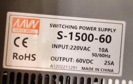
I bought two S-1500-60 "men well" 1500W / 60V switching supplies from aliexpress, which according to the seller should have 5V adjustable voltage and current.
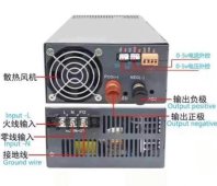
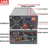
The 5V controllability was actually a add-on, originally they are shipped with potentiometers instead of the connectors (image attached). There are no datasheets or further information unfortunately
They seem to be solid built, but I don't get how the control voltage should work.
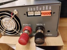
The connectors are labeled "VS+ / VS-" and "VCI/VC0", yet the connectors have three pins, which have actual voltage.
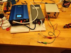
When initially turned on there was very little idle voltage, but measuring between the pins VS+/- seems to be enough to change the output voltage - I can slowly see how the control voltage drifts between 0-5v caused by the current of the DC meter, and that corresponds woth the 0-60V output as expected. This made me believe I understand what is going on, so I connected an adjustable constant voltage source to the VS+/-, but that didn't work.
Measuring from the middle pin of the VS+/VS- connector to the "left" one seems to reduce the voltage on the output (while the voltage on the control pins slowly increases), while measuring from the middle pin to the "right" one increaes the output voltage. I can't help but somehow it seems like this is no real 5V voltage controled input, but rather instead of the potentiometer a socket has been soldered in - with the 5V usually applied to the potentiometers.
I am a bit lost, any ideas how this could be supposed to work?
Thanks & best regards, Clemens
I bought two S-1500-60 "men well" 1500W / 60V switching supplies from aliexpress, which according to the seller should have 5V adjustable voltage and current.
The 5V controllability was actually a add-on, originally they are shipped with potentiometers instead of the connectors (image attached). There are no datasheets or further information unfortunately
They seem to be solid built, but I don't get how the control voltage should work.
The connectors are labeled "VS+ / VS-" and "VCI/VC0", yet the connectors have three pins, which have actual voltage.
When initially turned on there was very little idle voltage, but measuring between the pins VS+/- seems to be enough to change the output voltage - I can slowly see how the control voltage drifts between 0-5v caused by the current of the DC meter, and that corresponds woth the 0-60V output as expected. This made me believe I understand what is going on, so I connected an adjustable constant voltage source to the VS+/-, but that didn't work.
Measuring from the middle pin of the VS+/VS- connector to the "left" one seems to reduce the voltage on the output (while the voltage on the control pins slowly increases), while measuring from the middle pin to the "right" one increaes the output voltage. I can't help but somehow it seems like this is no real 5V voltage controled input, but rather instead of the potentiometer a socket has been soldered in - with the 5V usually applied to the potentiometers.
I am a bit lost, any ideas how this could be supposed to work?
Thanks & best regards, Clemens
Attachments
Last edited: