diy solar

diy solar

Seplos BMS Wiring Puzzle

weirded

New Member
Joined
May 8, 2021
Messages
145
I'm retrofitting a Seplos 200A BMS (V1 - bought a while back) to an existing 48V 16S 400Ah battery that came with our house (but had a rodent damaged BMS). The existing battery has a very nice set of terminals and a big contactor that I'm hoping to continue to use.
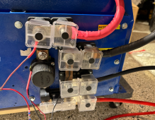
1703101774187.png

Trying to find the best way to go from there (ideally using 4/0) to the BMS, which has 3 battery terminals. I made a copper bus bar to connect the 3 battery terminals and was going to run one 4/0 to the center point (the smaller gauge wire in the pics is temporary to get the BMS booted up and validate my wiring).
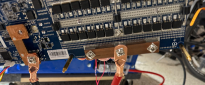
1703101940119.png
The same problem exists on the "inverter" side of the BMS, I want to run a single 4/0 into the system.

What are other options for wiring this up that I haven't thought about?
 
I'm retrofitting a Seplos 200A BMS (V1 - bought a while back) to an existing 48V 16S 400Ah battery that came with our house (but had a rodent damaged BMS). The existing battery has a very nice set of terminals and a big contactor that I'm hoping to continue to use.

View attachment 184179

Trying to find the best way to go from there (ideally using 4/0) to the BMS, which has 3 battery terminals. I made a copper bus bar to connect the 3 battery terminals and was going to run one 4/0 to the center point (the smaller gauge wire in the pics is temporary to get the BMS booted up and validate my wiring).

View attachment 184180
The same problem exists on the "inverter" side of the BMS, I want to run a single 4/0 into the system.

What are other options for wiring this up that I haven't thought about?
Hi Weirded... we’re trying to answer all unanswered threads... but I have no answer.... but good luck anyway.. hope someone with more knowledge turns up...
 
I'm retrofitting a Seplos 200A BMS (V1 - bought a while back) to an existing 48V 16S 400Ah battery that came with our house (but had a rodent damaged BMS). The existing battery has a very nice set of terminals and a big contactor that I'm hoping to continue to use.

View attachment 184179

Trying to find the best way to go from there (ideally using 4/0) to the BMS, which has 3 battery terminals. I made a copper bus bar to connect the 3 battery terminals and was going to run one 4/0 to the center point (the smaller gauge wire in the pics is temporary to get the BMS booted up and validate my wiring).

View attachment 184180
The same problem exists on the "inverter" side of the BMS, I want to run a single 4/0 into the system.

What are other options for wiring this up that I haven't thought about?

Would you have any opposition to running two 2/0 and splitting the difference by mounting in the middles between each of the 3 bolts?

Not sure what you refer to as 'same problem on inverter side'. With two 2/0 can invert one of the connectors so both ring terminals can be on the same mounting lug.

What is the max amps you will pass through this connection? Will it approach the 200a rating of the BMS?

Do you have more pictures or description to add some resolution to the dilemma?
 
Back
Top