diy solar

diy solar

Using an External Charger with Victron Multiplus II

jamiegreen

Solar Enthusiast
Joined
Nov 8, 2021
Messages
182
Just trying to wrap my head around this.. I'm upgrading my system to 48v, and will be using an external AC charger to charge from my generator, This is to prevent dirty passthru power supplying my loads. I'd like to accurately monitor the AC charger current and history, so I will fit a smart shunt between the charger and battery, although there is already a BMV 612 fitted I'd like to see this data separately and not have the system "guess" the charge current via inverter power deduction etc.

It would also be nice if the AC current of the generator could be monitored too, but without any passthru, I don't think its possible (correct me if I'm wrong) to have the generator connected to the Multi's AC IN and the separate AC charger connected to AC OUT 2, letting the Multi monitor the AC current to the external charger but still continuing to supply inverted power to my loads via AC OUT 1. If this isn't possible is there something that can be done with the Victron external CT clamp to monitor geni power?
 
Worth reading this post:


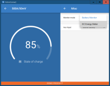
If you have a GX and are on VRM, configure the smartshunt as a "DC Energy Meter":

View attachment 140527

I can't comment on the CT sensor. Victron has a lot of options, but they seem to be integral to specific scenarios like having attached GT PV or other situation.

I think I've got the gist of the DC side, if I recall once DC meter is selected you can then select names such as "AC Charger" or "Solar Charger" etc. Monitoring the AC from the geni isn't crucial, more just a nice option for me, and I wont have an empty widget thingy on my CCGX then :)
 
I'd be happy if there's any other info on running a battery charger through AC OUT 2, whether there would be any sort of feedback loop.. I think just from factory default AC OUT 2 is only a grid passthrough with no inverter assistance (atleast not without setting up some sort of power assist) so I can't personally see a feedback loop issue, but I'd like to be sure. I believe the CT clamp can be used otherwise, and it should use this reading to monitor "grid".

..just out of curiosity, what  does happen if an inverter powered a charger that charged its own battery bank? I mean obviously it wouldn't charge, but would there be a disastrous failure?

Speaking of the DC smart energy meters, it seems at this time only the "solar inverter" name will show up as a tile in the GX device screen and none of the other options will, presumably because at this time they haven't designed tile placement for any of the other options a smart shunt can be used for (or whether they even will). Not an issue anyway..

AC OUT 2 = AC OUT 1 when AC IN is active.

In other words, a relay closes connecting AC out 2 to AC out 1 making them effectively the same.

If PowerAssist is enabled and conditions trigger it, it would also "boost" AC out 2.

The downside I see is everything is coming in through the ATS, so there's that limitation as well as the AC input limitation.

It would seem to make more sense to have the charger completely external.
I think that clears that up then.. seperate charger completely it is, I didn't realise the relay connected both outputs together. I'll probably have a play with the CT clamp to see exactly how that works.
Thanks
 
just out of curiosity, what  does happen if an inverter powered a charger that charged its own battery bank? I mean obviously it wouldn't charge, but would there be a disastrous failure?
This is how I initially tested my chargeverters.
I didn't care if it was productive. Just wanted to run them for a few hours to make sure they worked.
And it would have taken a long extension cord strung through the house to reach the grid.
 
Back
Top