diy solar

diy solar

Thinking about battery backup

Correct, they will be 34 in parallel (2 rows of 17 cells). What gauge wire should i use to connect the 14 in series?

150A draw/34 parallel = 4.4A. Almost any wire will do.
The question is what is the best mechanical or other connection method. Is there a way to manually connect busbars to the terminals? Or do you need a spot welder, which some posters have used?


Note the use of sheet metal rather than a gauge of wire. Maybe a sheet joined to positive of 2x17 cells and negative of next 2x17 cells.
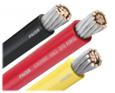
At the end of the stack you need a suitable way to adapt over to 2/0 cable without necking down to a cross section with less ampacity than about 125A. Could be a sheet of metal wide enough for 17 cells and long enough to wrap around stripped 2/0 cable. Then mechanically clamp in a bunch of places, or solder (BEFORE welding to batteries!) Have positive cable exit the pack going one direction, and negative cable going in the opposite direction, to balance draw from each string of cells.

What BMS? Get that wrong and you burn your house down, or at the very least kill cells.
 
When i look at the busbars HBPOWERWALL users on youtube they look pretty small, but the packs are massive.

1597934178347.png
 
150A draw/34 parallel = 4.4A. Almost any wire will do.
The question is what is the best mechanical or other connection method. Is there a way to manually connect busbars to the terminals? Or do you need a spot welder, which some posters have used?


Note the use of sheet metal rather than a gauge of wire. Maybe a sheet joined to positive of 2x17 cells and negative of next 2x17 cells.
At the end of the stack you need a suitable way to adapt over to 2/0 cable without necking down to a cross section with less ampacity than about 125A. Could be a sheet of metal wide enough for 17 cells and long enough to wrap around stripped 2/0 cable. Then mechanically clamp in a bunch of places, or solder (BEFORE welding to batteries!) Have positive cable exit the pack going one direction, and negative cable going in the opposite direction, to balance draw from each string of cells.

What BMS? Get that wrong and you burn your house down, or at the very least kill cells.


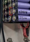
I plan to use Nickel Fused Strips from batteryhookyp to parallel the cells. Which will be spot welded to the batteries. Should i simply solder the series wire to the ends of each side or is it better to use a busbar soldered down the middle with a ring terminal like in the pic above? I purchased a 120a 14s BMS.

1597934540144.png 1597934769328.png

1597935151446.png
 
Last edited:
When i look at the busbars HBPOWERWALL users on youtube they look pretty small, but the packs are massive.

And I have put 1A through 30 gauge wire. Just because you can, doesn't mean you should.

That picture appears to show wire soldered to battery tabs. There is just one question you have to ask yourself: "Do I feel lucky?"
 
I plan to use Nickel Fused Strips from batteryhookyp to parallel the cells. Which will be spot welded to the batteries. Should i simply solder the series wire to the ends of each side or is it better to use a busbar soldered down the middle with a ring terminal like in the pic above? I purchased a 120a 14s BMS.

Best to solder that wire before spot welding, although the spirals should provide good thermal relief. And then I would solder the entire length.

That wire looks a bit skinny for 120A. I would at least use both ends, or better yet tap off more places like 7/8, 5/8, 3/8/ 1/8 along the pack, then match length of taps when bringing the together.

Ends? Measure narrowest cross section and look up ampacity.
Down the length is better.

How are the series connections made? I'd rather use the sheet metal edgewise, not lengthwise, for many times the cross-section.

Looks like there could be room for forced-air cooling between the cells (make sure that doesn't fool a temperature sensor.)
Clamping aluminum plates with heat sink compound between cells could be another option. Need to maintain spacing of sheet metal connections, though.
Temperature and state of charge/discharge are reportedly the key to long life.
 
Best to solder that wire before spot welding, although the spirals should provide good thermal relief. And then I would solder the entire length.

How are the series connections made? I'd rather use the sheet metal edgewise, not lengthwise, for many times the cross-section.

Thanks, ill be sure to solder it on before spot welding. I plan to connect them i series by attaching a ring terminal on the end of that copper wire that runs the full length of the battery. Il have the Positive come off the left and the negative off the right, then just bolt the Pos from one battery to the Neg of the next.

1597940256226.png
 
Thanks, ill be sure to solder it on before spot welding. I plan to connect them i series by attaching a ring terminal on the end of that copper wire that runs the full length of the battery. Il have the Positive come off the left and the negative off the right, then just bolt the Pos from one battery to the Neg of the next.

Is that someone else's pack, you haven't built yours yet?
I'd at least put ring terminals on both ends, for half the current through the wire and 1/4 the voltage drop (half the current, half the distance.)
........................................................................................................................................o...........o...........o...........o..... (ignore the dots added for formatting reasons)
You could make the wire tap off to ring terminals in four places: ___||______||______||______||___ for better results

If that was two, 12 awg twisted together, only suitable for about 40 maybe 60 amps. So four taps would be better.

Alternatively, if that sheet metal is for double-row batteries and you use it for single-row, it could stitch all the batteries in series as well as parallel. That'll probably leave 50% air space unless you get clever either interleaving parallel sets or pre-creasing the sheetmetal and then folding over after welding.

Those arent my packs, just pics that look similar to what i want to do. They would look something like this with just a single bar down the middle, soldered to the Nickel Fuse plate.
1597944106609.png
 
Is that someone else's pack, you haven't built yours yet?

When i look at the busbars HBPOWERWALL users on youtube they look pretty small, but the packs are massive.
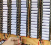
Yes, those are the buss bars within each module but they join together in the ring terminals in what I would guess are about 1/0 more or less. He uses a loop to reduce any resistance to the parallel batteries at the end of his copper buss bars. The current is shared around the loop so my guess is the current carrying capacity would be like two wires I didn't pick up on his Amperage when I watched a few of his videos, but he really thought it through.
 
Yes, those are the buss bars within each module but they join together in the ring terminals in what I would guess are about 1/0 more or less. He uses a loop to reduce any resistance to the parallel batteries at the end of his copper buss bars. The current is shared around the loop so my guess is the current carrying capacity would be like two wires I didn't pick up on his Amperage when I watched a few of his videos, but he really thought it through.

His batteries are about 170ah each. He did a 30amp continuous discharge and they did get warm (34c/94f), but not enough to trip anything.
I cant do a loop unfortunately as mine are 2 cells wide. Unless i go to 36p (3x12). But i dont have enough cells for that.
 
Last edited:
Ring terminals 1/0? Looks like the wires are around 10 awg, and two connect to the ring terminal which is only at one end of the pack.
10 awg can carry 30 or 40 amps reasonably, so two would be 60 to 80 amps. Put a ring terminal at each end of the back for double, 120 to 160A.

You've only got two rows of batteries, one wire down the middle. So tap it off four places like I suggested. Then each 10 awg (or two 12 awg twisted) only carries 1/4 of the current.

You could do 2x11 + 12 = 34

Or arrange your cells as one row of 34 cells. Put the next row of 34 flipped upside down. Then the sheet metal jumpers between their positive and negative terminals. Only at the end ones do you need to tap wires appropriately. That could be 17 pieces of 16 awg stranded, all the same length. Or one piece of 2/0 battery cable stripped as long as the sheet metal, or unraveled into many smaller stranded wires to fan out.
 
Ring terminals 1/0? Looks like the wires are around 10 awg, and two connect to the ring terminal which is only at one end of the pack.
Are we looking at the same pictures? The pictures I am looking at have the guys hand on them. I would guess the size of the wires going into the ring terminal as one half the width of his thumbnail. In the end it doesn't matter what the guy in Australia did, it matters what @MASolarGuy is going to do.
 
Correct, the pics of the other guys packs was just for perspective on what im doing and how it would look. With mine being only 2 cells wide, only one strand of wire till fit down the middle. I understand what you are saying hedges with the taps, but i would much rather use a single wire is possible.
 
I think we're looking at the same picture. Here is what I saw:

1597953300416.png

That wire looked fairly skinny to me.

MASolarGuy could run 1/0 down every strip, but that would be fairly ridiculous.

@MASolarGuy - if you only want to use one wire, what gauge? You can look up ampacity tables for single wire in free air to get a fair idea. Then if you are planning to run higher current, estimate the temperature rise it would cause considering power goes as the square of the current.

e.g. if 10 AWG single wire ampacity is 55A for 60 degree rise from 30C to 90C, then if you run 2x the current (110A), you'll get 2^2 = 4x the rise. 4 x 60 + 30 = 270C. The copper would take that, but solder wouldn't and neither would the battery. Your actual mileage might not be as bad because only at the last couple cells would current be that high, and heat spreads through length of the wire which acts as a heat sink.

I can take a stab at analyzing what you do, but need wire gauge, current, and connections/dimensions. I don't really do a formal analysis of thermal, but scale off ampacity charts and similar sources.

How about just using the sheet metal to join all cells, no wires?
 
I think we're looking at the same picture
No, I am looking the picture at this post.

I agree with the advice you are giving. I don't know what guage wire @MASolarGuy is planning on using but the purpose of it is to carry more Amps than the nickel strips as we saw in the pictures of the other packs. That buss wire was soldered to the nickel strips.

Would the nickel strip also be included in the equation as it will also be carrying Amps?
 
Would the nickel strip also be included in the equation as it will also be carrying Amps?
Somewhat but I don't know how much. Are you using the kind that has the small fusible links like in HBPOWERWALL's build. Hedges has the best technical knowledge in this area. I have just been trying to clarify understanding of what I saw from that other build which was well thought through.
 
Somewhat but I don't know how much. Are you using the kind that has the small fusible links like in HBPOWERWALL's build. Hedges has the best technical knowledge in this area. I have just been trying to clarify understanding of what I saw from that other build which was well thought through.


Yes, each sell will have its own fuse using the battery hookup fused nickel sheets. I believe they pop at anything over 10amps directly to the cell. Thr copper wires job (if im understanding things) is to help even the draw across the whole strip, handle the amps, and provide a way to connect the strips in series.
1597957123565.png
 
"Yes, each sell will have its own fuse using the battery hookup fused nickel sheets. I believe they pop at anything over 10amps directly to the cell."

Ahh, so there is method to their madness! And here I thought that was just mechanical flexibility, which also happens to provide thermal relief if you do solder.

Is that supposed to be nickle throughout, not just nickle plated something else?
If you can identify it you can maybe find its ampacity.
Perform 4-wire resistance measurement to be able to calculate voltage drop across it. The geometry is tough, but could could measure from battery terminal to body of strip, also end to end. The end to end resistance would be real good to calculate voltage sag along the strip. Just build a ladder in Excel of cell current and strip resistance. Add the copper wire in parallel.
You may find that at 120 amps there is a significant voltage difference between cells due to not having perfectly balanced resistance.

Yes, the nickle strip has its own ampacity restrictions and resistance. Eyeballing those wasp waists vs. the spiral fuse, they can't handle more than 100A. If someone tapped off the end for 125A without soldering a copper wire along the way, it would pop.

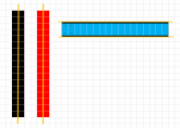
I still say the best assembly would be to use one row of that strip for a row of 34 battery positive terminals, and the other row for a row of 34 battery negative terminals. Then for the terminals at last group of batteries each end, unravel a 2/0 battery cable, insulate each twisted bundle, and solder each one to the strip between cells 1&2, 3&4, etc. That will provide absolutely perfect symmetry.

It appears 2/0 has 19 twisted groups. For 34p arrangement of cells you would connect 17 of those.

1597964453816.png
 
Back
Top