energyhunter
New Member
- Joined
- Feb 20, 2022
- Messages
- 93
With thanks to Will Prowse for creating this forum, I would sure appreciate any help here proofing my "wiring" scheme....
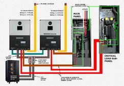
This is an upgrade from an EG4 6500 split phase system that has been running fine for over a year, but for longevity reasons I'm going with the 6000XPs. My son and I will be switching out the inverters in a few days so I've put together a DIY friendly diagram for those of us that have more challenges with traditional schematics. (FYI- The inverter connections are straight forward in countless videos which is why I have not pictured them. The symbolic conduit depictions vary in color for readability and in width to accommodate showing the 4 colored THHN stranded wires and also their relative widths as they enter the inverters.)
This is an off-grid split phase system using the utility as a backup when short on sunshine and battery storage. It is powered by 21 roof-mounted Solarever panels 440w each. I prefer adding a whole house xfer switch to be back on the grid while addressing any problems with the solar system, but my budget is limited for now. I had already migrated all the 120v circuits to the sub-panel for the previous setup. The main panel has four 240v circuits, two of which I will move now to the sub-panel. Before proceeding we need to know:
(1) Are there any glaring and embarrassing errors right off??
(2) Is the neutral/ground bond format correct?
(3) Does the AC in and out (Black L1, Red L2) have breakers and wire gauges sized adequately and are their respective neutrals/white and grounds/green landed in the right places in the Main and Sub-Panel?
(4) Given the serial strings we have, are we still within the 480v limit of the 6000XPs in our eastern TN climate? (We were within the 500v limit of the 6500EXs.)

")