iClick
New Member
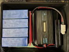
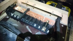
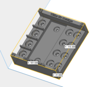
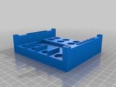
I'm considering purchasing a 3D printer (Creality Ender-3 V3 SE) and using it to print (amongst other things) parts for my solar builds. The first project that has driven this idea is for a custom bus bar incorporating ANL fuses. The file can be viewed here: Thingiverse Fuseholder for 5x40 copper bar
I'd like the bus bar to handle at least 400 amps but I'm unsure of the most appropriate filament to use as I understand that not all are completely non-conductive if they contain certain additives. My other concern is what may happen if there was excessive heat (above 70ºC) to the structure. Would it start to melt/deform and cause issues?
I like the idea of being able to manufacture cable guides, terminal protectors, BMS holders and so forth but only if safety concerns are addressed.
If anyone has successful experience in 3D printing high current parts I'd love to hear your feedback. (Also, if the Creality printer I linked above would be a good 1st printer for a newbie)
EDIT: extra images
Attachments
Last edited: