diy solar

diy solar

Swapping out

execv

New Member
Joined
Jul 16, 2023
Messages
13
Location
Utah
Hello,

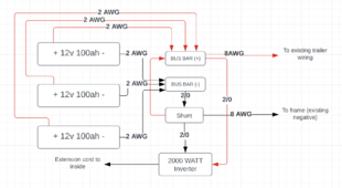
I'm swapping out my 2x lead acid batteries on my trailer with 3x Lifepo4 batteries (and adding a shunt/inverter), and I wanted to get some input. The trailer currently has 8 AWG wire going from the battery (positive) to the disconnect. I am wanting to add a 2000 watt inverter. From what I've read online, I should use 2/0 wire. My questions are:
  1. I need to use 2/0 wire between each battery, to the shunt, and to the inverter, correct? I've read conflicting suggestions of being able to use 1/0 or 2 AWG. I'll only be using this to charge laptops and occasionally make coffee.
  2. I've read that all of the cable lengths should be the same between the batteries. Can I use 1' between each battery, but then 2' or 3' from the negative terminal to the shunt (due to space issues the batteries have to be oriented as they are in my diagram). Should I use the same length from the final positive lead to the bus bar?
  3. Can I use 8 AWG to then run to the existing wiring in my trailer (negative to the frame and positive to the disconnect)?
  4. Can I connect the 2/0 wire and the 8 AWG to the trailer to the end of the shunt, or does this need to have a bus bar?
  5. Is there anything incorrect, wrong or missing in my plan? I know it's probably ideal to add a fuse between the bus bar and the inverter.

Screenshot 2024-04-23 at 2.30.50 PM.png
 
If you wire EACH battery to the Busbar, then you can use a smaller wire for battery to busbar. If you wire as drawn, then the full current flows through all the wires, and all the wires should be rated to handle the entire load.
 
If you wire EACH battery to the Busbar, then you can use a smaller wire for battery to busbar. If you wire as drawn, then the full current flows through all the wires, and all the wires should be rated to handle the entire load.
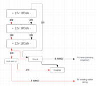
That makes sense. What would the recommend size wire be if I were to write each battery to the bus bar? I'm assuming I'd still need 2/0 from the busbar to the inverter though.
 
From reading Will's book, it sounds like I could safely use 2 AWG to go from the batteries to the bus bar, and then use 2/0 to the inverter. Is htis correct?Screenshot 2024-04-25 at 1.00.35 PM.png
 
Another thing on the wire lengths is that the Positive wires should be the same length, and the Negative wires should be the same length, but the Positive wires don't have to be the same length as the Negative wires.

You'll likely be stuffing wire somewhere.
 
Does anyone have any feedback on the size wire I should use between the batteries and the bus bar?
 
30 amp. The trailer is currently wired with 8awg. I am not changing that (I will connect 8awg to the existing fuse that powers the trail).
 
30 amp. The trailer is currently wired with 8awg. I am not changing that (I will connect 8awg to the existing fuse that powers the trail).
Coolio

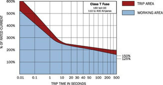
2 ga is the correct size for the batts to the buss bars. It is good for 175A. Put a 200A MRBF fuse on each battery positive. You also need a fuse between the positive bus bar and the inverter. 250A is fine. I like class T for this part. DO NOT use a breaker/fuse for this part. IMHO. There should already be a fuse protecting the 8 ga wire on your existing system, but if not, put a 60A fuse/breaker on that.

I do not like frame grounded DC systems on campers. I know they wire them that way, but boo hiss. Your converter output should have a negative wire coming off of it and running to your power panel. That is then connected to the frame. That is only there to frame ground the AC side of the power panel. It has the side effect of connecting the battery negative to the frame as well. But nothing in a trailer should use the frame as the negative path for current.

Having said all that, where is your current battery negative connected? I have never seen a new trailer where the battery negative is attached to the frame.

Do yourself a huge favor and get an inverter with a 30A auto transfer switch. Then just wire the inverter output to your existing power panel AC input. Should be really easy to just splice the inverter into your existing shore power line. The extension cord will get old. Doing it this way will allow you to power anything as long as it doesn't overload the inverter. BUT, you MUST remember to turn off the converter breaker when on battery + inverter power. If you forget, the battery will try to charge itself. Not a blue smoke event, but very inefficient.
 
Does anyone have any feedback on the size wire I should use between the batteries and the bus bar?
Really depends on how many amps your inverter is rated for and then divide that by three is you want the battery to be shared on three batteries, two batteries in case one is bad, or drop to one battery.

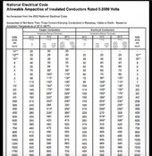
I use this chart to determine wire size, and then check manufacturer specs.

IMG_1348.jpeg
 
Really depends on how many amps your inverter is rated for and then divide that by three is you want the battery to be shared on three batteries, two batteries in case one is bad, or drop to one battery.

I use this chart to determine wire size, and then check manufacturer specs.

View attachment 211693
When I design a system, I assume that a single battery may have to power the whole system. In this case, a 2000W inverter is 175A from a single battery. If the BMS cannot handle that, then size the wire for the BMS max output.
 
When I design a system, I assume that a single battery may have to power the whole system. In this case, a 2000W inverter is 175A from a single battery. If the BMS cannot handle that, then size the wire for the BMS max output.
So for your 2 gauge recommendation, what wire type for 175 amps? Mostly looking for insulation rating and ampacity of the wire. Chart I posted has 90c wire rated to 150, so 185 anmps exceeds that NEC chart. Perhaps TEMCO welding wire has a max amperage that high.

Also, with the 175 watts for a 12 volt inverter, does this include dc to ac efficiency, typically 85%, or a low voltage inverter cutoff. Using those, I get 235 amps. That’s also with no efficiency losses.

I suspect a 100 amp cutoff for a BMS with 100 ah, so for that BMS to battery 2 AWG should be fine.
 
I suspect a 100 amp cutoff for a BMS with 100 ah, so for that BMS to battery 2 AWG should be fine.
I have 3 of these. It does have a BMS but it does say "Discharge Current: 100amp. Max Discharging Current: 280 amp (5 second). Should I maybe put a 150amp fuse on each battery then to help protect this?
 
Last edited:
2 ga is the correct size for the batts to the buss bars. It is good for 175A. Put a 200A MRBF fuse on each battery positive. You also need a fuse between the positive bus bar and the inverter. 250A is fine. I like class T for this part. DO NOT use a breaker/fuse for this part. IMHO. There should already be a fuse protecting the 8 ga wire on your existing system, but if not, put a 60A fuse/breaker on that.
Ok awesome, this helps a lot. Thanks!

Yes, the 8 AWG that goes to the trailer goes directly to a fuse for the trailer. The additional items I am adding are just for the inverter.
 
I have 3 of these. It does have a BMS but it does say "Discharge Current: 100amp. Max Discharging Current: 280 amp (5 second). Should I maybe put a 150amp fuse on each battery then to help protect this?
1714176566178.jpeg
If your wire is rated for 150 amps, fine.

A 100 amp would be better IMO. That would blow around 3 seconds at 280 amps. You don’t really want the BMS surging to 200plus amps for several seconds.

I use the Blue Sea circuit wizard for designing.


Yes, 175A is 2000W / 0.84% efficiency / 13.6V.
I’ve always felt the wires in that are way too skinny. Blue Sea’s recommendation calls for thinner wires than NEC’s charts have ampacity. I would not want to run 2000 watts for very long times with that.

I wonder if blue sea makes those charts with someone in mind who occasionally warms a microwave up on a boat with a 2000 watt fully charged battery, versus NEC where large sustained amperage goes through the wires hours on end.

For a 2000 watt inverter on my RV at 12 volts, I used 4/0 inverter to battery and 2/0 between both batteries. My calculations for a 2000 watt 12 volt scenario was 257 amps. 90 c 5/0 wire is rated for 260 amps.

Total amperage formula I used.

Inverter rated wattage / Low Voltage cutoff / inverter efficiency * 1.15 safety factor

257 amps = 2000 watts / 10.5 volts / 85% *1.15

Two out of the three boondocking campsites I went to this year had RVs burned to their frames. I have no idea what caused it, but I can wire thick.

I also have the “guest/family” factor where they will break any limits I hav, such as leaving the install plugged in at 1000 watts and not wake me up when the battery monitor beeps low voltage.
 
How far will your inverter be for m.your batteries? That will help dictate the size of your inverter wiring.
 
View attachment 211706
If your wire is rated for 150 amps, fine.

A 100 amp would be better IMO. That would blow around 3 seconds at 280 amps. You don’t really want the BMS surging to 200plus amps for several seconds.


I’ve always felt the wires in that are way too skinny. Blue Sea’s recommendation calls for thinner wires than NEC’s charts have ampacity. I would not want to run 2000 watts for very long times with that.

I wonder if blue sea makes those charts with someone in mind who occasionally warms a microwave up on a boat with a 2000 watt fully charged battery, versus NEC where large sustained amperage goes through the wires hours on end.

For a 2000 watt inverter on my RV at 12 volts, I used 4/0 inverter to battery and 2/0 between both batteries. My calculations for a 2000 watt 12 volt scenario was 257 amps. 90 c 5/0 wire is rated for 260 amps.

Total amperage formula I used.

Inverter rated wattage / Low Voltage cutoff / inverter efficiency * 1.15 safety factor

257 amps = 2000 watts / 10.5 volts / 85% *1.15

Two out of the three boondocking campsites I went to this year had RVs burned to their frames. I have no idea what caused it, but I can wire thick.

I also have the “guest/family” factor where they will break any limits I hav, such as leaving the install plugged in at 1000 watts and not wake me up when the battery monitor beeps low voltage.
Hmmm, maybe I need to rethink my recommendation of the Blue Sea circuit wizard. My issue is the NEC standards for 4/0 mean my 4/0 wire to my 3000W inverter are woefully undersized and that makes no sense to me.
 
I think I found the difference between NEC ampacity and ABYC that Blue Sea uses. The NEC charts are based on "Not More Than
Three Current-Carrying Conductors in Raceway, Cable, or Earth (Directly Buried)." The Blue Sea Systems calculator uses ABYC standards for single conductor in free air. IMHO, the single conductor in free air seems to fit my application better than the NEC one.

21731.jpg
 
Coolio

2 ga is the correct size for the batts to the buss bars. It is good for 175A. Put a 200A MRBF fuse on each battery positive. You also need a fuse between the positive bus bar and the inverter. 250A is fine. I like class T for this part. DO NOT use a breaker/fuse for this part. IMHO. There should already be a fuse protecting the 8 ga wire on your existing system, but if not, put a 60A fuse/breaker on that.

I do not like frame grounded DC systems on campers. I know they wire them that way, but boo hiss. Your converter output should have a negative wire coming off of it and running to your power panel. That is then connected to the frame. That is only there to frame ground the AC side of the power panel. It has the side effect of connecting the battery negative to the frame as well. But nothing in a trailer should use the frame as the negative path for current.

Having said all that, where is your current battery negative connected? I have never seen a new trailer where the battery negative is attached to the frame.

Do yourself a huge favor and get an inverter with a 30A auto transfer switch. Then just wire the inverter output to your existing power panel AC input. Should be really easy to just splice the inverter into your existing shore power line. The extension cord will get old. Doing it this way will allow you to power anything as long as it doesn't overload the inverter. BUT, you MUST remember to turn off the converter breaker when on battery + inverter power. If you forget, the battery will try to charge itself. Not a blue smoke event, but very inefficient.

Three batteries in parallel put the MRBF fuses and holders at the bus bar end.

If you get a short on the cables or across the posts of a single battery the current from all three batteries will flow through the wires and potentially melt the insulation.

I've done the math in another thread and with 4 batteries the insulation melts in 0.1 seconds. With 3 the fuse on the shorted battery fuse blows and the wire is just hot.

Putting the fuse at the bus bar end avoids this. Ideally you would fuse both ends of the battery wires, but most people don't and depend on the BMS to cut the current.

Then put a class T or another MRBF at the bus bar to the inverter. And another fuse to the rest of the wiring also at the bus bar. Also make sure the shunt power wire is fuses. Usually 1 amp.


Also do yourself a favor and check that the bus bars are real and can handle the current. Measure the end of the bar in mm to find the cross section area. Now take a file and file off the corner through the plating and see if it is copper or brass. Make sure to go deep enough, they typically plate brass with copper then nickel. If copper multiply by 4.92 if brass 1.86, this gives you the ampacity of the wire. If the bar says it is plated brass you can skip the filing but still do the math.

There are a ton of bars on amazon that say 300 amps that won't carry 100 amps. And there are many that claim to be copper but are actually brass.
 
Back
Top