diy solar

diy solar

Solar Recommendations and Thoughts

JReich2609

New Member
Joined
Mar 26, 2024
Messages
15
Location
Oregon
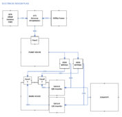
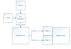
This is a quick and dirty drawing of the proposed wiring on new construction.
1716136874539.png

We have placed the Generator at the 400 AMP feed with an appropriately sized ATS because there is pumping equipment that needs to be powered in the event of a power outage in the pumphouse itself. So by having the power generator there we can feed down the system.

My question is where is the best place to hook solar into this system. Would I hook a Sol-Ark or example into each 200 AMP panel, or one that feeds both panels (if that is even possible). We don't have a real need/desire to store power for use this is just to offset use in real-time so likely an AC coupled system.

But my experience in this area is minimal so just looking for thoughts/insights. We have a reasonably high power demand so the system will be sized appropriately. And would having solar production and the generator running simultaneously be a problem? As in this design I am not sure if we'd need the GEN and SOLAR to talk to each other, or not?

Thanks all for your thoughts!
 
I think you are saying:
No battery storage.
The pump house is a critical load so needs the generator.
It is ok if only the house gets solar.
The goal is reducing purchased power.
If true, I suggest two inverters with 200 Amp pass thru, one for each 200A house panel and you could easily add battery in the future. This way there would be no hard to start pump loads on the inverters. Installation would only require intercepting the feed to the existing panels.
Edit: Another question, is the generator only powering the pump house or everything, if everything it must be a big generator.
 
Last edited:
I think you are saying:
No battery storage.
The pump house is a critical load so needs the generator.
It is ok if only the house gets solar.
The goal is reducing purchased power.
If true, I suggest two inverters with 200 Amp pass thru, one for each 200A house panel and you could easily add battery in the future. This way there would be no hard to start pump loads on the inverters. Installation would only require intercepting the feed to the existing panels.
Edit: Another question, is the generator only powering the pump house or everything, if everything it must be a big generator.
Yes, Yes, Yes, and Yes!

The generator will be a 100 amp 24kw propane generator. Sufficient for power a 400 amp load, no. But this isn't a commercial operation and the size wire has more to do with future-proofing than need. Also systems that draw significant amps (electric car charger for example) tend to disable themselves in the time between outage, and generator recovery. Always look at load shedding, etc., as well.

If I run two inverters for each panel load do you take the total size and split it in half for each leg, or just but a large inverter on each side, so there is no problems down the road?

I assume if we are talking batteries down the road we would be looking at a DC coupled solution.
 
My suggestion would be an EP Cube system with 7.6KW inverter and at least 9.6KWH on each 200A panel. The minimum battery is 9.9KWH up to 39.6KWH per inverter. With 2 Cubes your house would have 15.2KW of inverter and 19.2KWH up to 79.2KWH (easily expandable- just stack up) of battery. Each inverter has 200A pass thru, meaning the 200A grid power connects to inverter then on to the house distribution panel. The EP Cube system can be installed outdoors or indoors. The EP Cube is an all-in-one hybrid (complete system except the PV stuff), and it is DC coupled so very efficient charging batteries from PV. I'm pro EP Cube because I just bought one last week, all 1,200lbs of it will be here on Wednesday. Mine is 15.2kW inverters and 39.6KWH battery. Check out the EP Cube at Signature Solar, you will like it and if you study the features, you will find it is more capable and much cheaper than the latest Tesla Powerwall 3. It is a Canadian Solar product. Don't know if you qualify for any rebates in Oregon but here in California there was one and then the 30% fed deduction applies too. I'm stunned what my net cost will be.
I have family in Oregon, I like to say they are "circling" Drain.
 
Last edited:
New thought: The 100A from the generator could be wired w/50A to each inverter. Either of the inverters could auto start the generator and you wouldn't need any transfer switch at all. Would provide 10ms transfer from grid to battery & start the generator. I have a 10KW stationary propane generator & dedicated 299gal. propane tank & it will be controlled by and feed to my Cube.
 
If I run two inverters for each panel load do you take the total size and split it in half for each leg, or just but a large inverter on each side, so there is no problems down the road?

I don't believe there are many residential solutions for > 200A bypass. I did a quick search for 400A Microgrid Interconnection Device (MID), the official NEC term, and I saw some Enphase threads were people were not super happy at the lack of a product from that ecosystem. And the MIDs I've seen for hardware people talk about here top out at 200A.

I'm not sure what you mean by two inverters

My question is where is the best place to hook solar into this system. Would I hook a Sol-Ark or example into each 200 AMP panel, or one that feeds both panels (if that is even possible). We don't have a real need/desire to store power for use this is just to offset use in real-time so likely an AC coupled system.
(Usually when people say Sol-Ark they are also installing a battery in a DC coupled setup, so I will assume that's what you meant)

AC coupled means something else -- how the solar power is integrated with your batteries. DC coupled means they meet up with your battery via DC. AC coupled means they're converted to AC first (typically via grid tie inverters or microinverters that you either already have from an existing installation, or were horrifically forced to use because of shading. I have the latter situation and really shouldn't have purchased solar, but here I am for the engineering challenge). And then the battery itself has an AC interface to the solar.

If you just want to offset use, you do not need anything as fancy as a SolArk 15K or EG4 18kpv with 200A bypass. You can strategically place CT sensors (Current Transformer) to enable the inverters to detect the amount of power used by your houes, and set the inverter to self consumption mode. An important technical detail is talking to the support engineers at those companies to tell you how to pick the right CT and settings to handle 400A (they probably ship with 200A CTs), but this is far simpler than finding a 400A MID (could be that Googling was the wrong approach, and you calling a supplier can help you find one. MIDs are not cross-vendor compatible as of this writing, so it's going to be rough.). And, by installing the CT at the common location above your two 200A panels, inverters in front of either panel can offset the loads from the other panel.

If you have net metering or billing across say 1 hour averaging buckets instead of minutes or instant buckets, that allows you to undersize further, because burst usage above your inverter's AC output capability can be compensated for later, and your power company will credit you back.

But my experience in this area is minimal so just looking for thoughts/insights. We have a reasonably high power demand so the system will be sized appropriately. And would having solar production and the generator running simultaneously be a problem? As in this design I am not sure if we'd need the GEN and SOLAR to talk to each other, or not?
How have you measured your power demand? If you are using NEC load calculations for new construction, you will grossly oversize your inverters. Typically people recommend doing an energy audit with an energy meter, and this will come out much lower. And given that it is new construction, you can pick appliances like HPWH, HP dryers that can reduce the load calcs. (HP = Heat Pump).

AC coupling (as I defined it - grid tie to a battery, not as you defined it I think) is anathema to running a generator directly, because there are then too many incompatible AC waveforms to sync. Either the solar needs to be DC coupled, the generator integrated via a DC charger, or some kind of transfer switch interlock set up between the AC coupled solar and the generator. Of these three, only the DC coupled today comes as a turn-key solution. The other two are certainly technically feasible with redneck tier power engineering expertise (I could be exaggerating as an engineer in a different discipline 🤷), but it requires a certain level of technical expertise to understand the theory of operation enough to DIY, get it working, and ongoing operational knowledge to keep it working.

Also, I'm confused. You said you just care about offset use in real time. But I think this is a white lie, because you also have a generator, which implies you want storm / grid outage resilience. In this case, you want to size the inverters to match the emergency power load that you need. And, because of the 200A MID limitation on residential hardware in 2024, the inverters will only be able to supply emergency power to the half of your 400A that they are installed into.
 
My suggestion would be an EP Cube system with 7.6KW inverter and at least 9.6KWH on each 200A panel. The minimum battery is 9.9KWH up to 39.6KWH per inverter. With 2 Cubes your house would have 15.2KW of inverter and 19.2KWH up to 79.2KWH (easily expandable- just stack up) of battery. Each inverter has 200A pass thru, meaning the 200A grid power connects to inverter then on to the house distribution panel. The EP Cube system can be installed outdoors or indoors. The EP Cube is an all-in-one hybrid (complete system except the PV stuff), and it is DC coupled so very efficient charging batteries from PV. I'm pro EP Cube because I just bought one last week, all 1,200lbs of it will be here on Wednesday. Mine is 15.2kW inverters and 39.6KWH battery. Check out the EP Cube at Signature Solar, you will like it and if you study the features, you will find it is more capable and much cheaper than the latest Tesla Powerwall 3. It is a Canadian Solar product. Don't know if you qualify for any rebates in Oregon but here in California there was one and then the 30% fed deduction applies too. I'm stunned what my net cost will be.
I have family in Oregon, I like to say they are "circling" Drain.
I will look into it. I am not super concerned with adding on batteries up front, anyway.
New thought: The 100A from the generator could be wired w/50A to each inverter. Either of the inverters could auto start the generator and you wouldn't need any transfer switch at all. Would provide 10ms transfer from grid to battery & start the generator. I have a 10KW stationary propane generator & dedicated 299gal. propane tank & it will be controlled by and feed to my Cube.
Could. We will have a 250-gal propane tank. The problem is that the inverter(s) would be on the house and not at the pump house, where the generator will be installed. There is no practicality in legging them straight to the inverters, plus, I believe that would defeat the intent to keep the pumphouse powered.
How much load in pumphouse & how big is biggest motor? Does biggest motor have a variable speed drive or soft start?
Great question. As this is all theoretical, everything is subject to change. On a typical day, not much. Well pump, likely an RV plug, and perhaps feeds from that location to lighting around the property (or it may come off the house). However, no matter what, the Well and RV plug and a generic set of outlets for the 10 x 10 building are given.

The biggest motor. The most significant single-source power draw would likely be a 100-amp electric car charger.
After that, we run the data center server equipment on several racks. This is a consistent, steady draw of power, and it wouldn't hurt me to measure precisely what the draw is, which I'll do here at some point. However, the equipment will grow and likely not shrink.

And we are circling the Woodburn/Molalla area - further North, but I got it!
 
I don't believe there are many residential solutions for > 200A bypass. I did a quick search for 400A Microgrid Interconnection Device (MID), the official NEC term, and I saw some Enphase threads were people were not super happy at the lack of a product from that ecosystem. And the MIDs I've seen for hardware people talk about here top out at 200A.

I'm not sure what you mean by two inverters


(Usually when people say Sol-Ark they are also installing a battery in a DC coupled setup, so I will assume that's what you meant)

AC coupled means something else -- how the solar power is integrated with your batteries. DC coupled means they meet up with your battery via DC. AC coupled means they're converted to AC first (typically via grid tie inverters or microinverters that you either already have from an existing installation, or were horrifically forced to use because of shading. I have the latter situation and really shouldn't have purchased solar, but here I am for the engineering challenge). And then the battery itself has an AC interface to the solar.

If you just want to offset use, you do not need anything as fancy as a SolArk 15K or EG4 18kpv with 200A bypass. You can strategically place CT sensors (Current Transformer) to enable the inverters to detect the amount of power used by your houes, and set the inverter to self consumption mode. An important technical detail is talking to the support engineers at those companies to tell you how to pick the right CT and settings to handle 400A (they probably ship with 200A CTs), but this is far simpler than finding a 400A MID (could be that Googling was the wrong approach, and you calling a supplier can help you find one. MIDs are not cross-vendor compatible as of this writing, so it's going to be rough.). And, by installing the CT at the common location above your two 200A panels, inverters in front of either panel can offset the loads from the other panel.

If you have net metering or billing across say 1 hour averaging buckets instead of minutes or instant buckets, that allows you to undersize further, because burst usage above your inverter's AC output capability can be compensated for later, and your power company will credit you back.


How have you measured your power demand? If you are using NEC load calculations for new construction, you will grossly oversize your inverters. Typically people recommend doing an energy audit with an energy meter, and this will come out much lower. And given that it is new construction, you can pick appliances like HPWH, HP dryers that can reduce the load calcs. (HP = Heat Pump).

AC coupling (as I defined it - grid tie to a battery, not as you defined it I think) is anathema to running a generator directly, because there are then too many incompatible AC waveforms to sync. Either the solar needs to be DC coupled, the generator integrated via a DC charger, or some kind of transfer switch interlock set up between the AC coupled solar and the generator. Of these three, only the DC coupled today comes as a turn-key solution. The other two are certainly technically feasible with redneck tier power engineering expertise (I could be exaggerating as an engineer in a different discipline 🤷), but it requires a certain level of technical expertise to understand the theory of operation enough to DIY, get it working, and ongoing operational knowledge to keep it working.

Also, I'm confused. You said you just care about offset use in real time. But I think this is a white lie, because you also have a generator, which implies you want storm / grid outage resilience. In this case, you want to size the inverters to match the emergency power load that you need. And, because of the 200A MID limitation on residential hardware in 2024, the inverters will only be able to supply emergency power to the half of your 400A that they are installed into.
Lots of important information here. I agree that a DC-coupled setup makes sense.
I am leaning towards a 12k Sol-Ark on each 200 amp feed or a similar vendor/manufacturer outcome.

See the information above concerning some of the electrical uses. And yes, all of the appliances and things in the house will be as energy-efficient as possible. We are not far enough into the construction process to have a ton of specifics yet, but think LED lighting throughout, high-efficiency ducted mini-splits, etc. We will likely have an induction cooktop, which would be a big (short-term) power draw.

Offset is the goal. But as to my point above, we run server equipment with critical loads, so we do care about disruption. I just don't specifically care about offsetting that disruption with batteries in tandem with a solar system.
 
You want the generator to keep pump operating, but if pump + household loads exceed generator capacity it will shut down.
You will have to manually disconnect loads and try again.

How about putting ATS on the branch at pumphouse feeding pump. Also run an additional wire to backed up loads at the house.

You have 400A (100kW) service to the property, ATS to 100A (25kW) generator, 2x 200A (50kW each) service to house, considering 2x 50A (12kW) SolArk.
By sizing loads always connected to generator and to inverters, they will be able to keep running (given batteries and PV) for a while.

You can have manually interlocked breakers (like a transfer switch) to also backfeed 200A loads panels after manually turning off excessive loads, in case there is something else you want to operate.

If not using batteries, you don't need SolArk or its internal 200A relay. (And by the way, you should have external switch or interlocked breakers to bypass SolArk in case it fails.)
For just GT PV backfeeding grid for net metering, you can use a Sunny Boy (now discontinued), Fronius, or other PV only inverter. BUT, needs to feed back to grid connction before ATS, so it doesn't backfeed generator.

Yes, there is an issue with generator + PV, don't want to backfeed generator. So in this case, SolArk does serve a purpose, can prevent backfeed. I'm not sure the details; it has a "Gen" port which can serve that purpose. When generator goes to transfer switch into "Grid" input, how do you tell SolArk to prevent backfeed (question for SolArk users)? I use Sunny Island, which has an input to signal generator vs. grid.


Plan your various loads:
Critical (on UPS, never go down) for communications
Important (backed up after a delay) refrigeration, some lights
Convenient (powered when available) A/C, laundry
Unimportant (never backed up except by manual invervention)

Design wiring branches so generator, battery + PV, transfers switches, interlocked breakers let you power these as desired.
Battery inverter could be a later addition (or battery on your hybrid inverter) by separate the circuits to let this be done.

If you have multiple breaker panels with a wiring gutter below them, and suitably long "service loops" of extra wire length, you can pull wires off breaker in one panel and rearrange in case you change your mind.

Have multiple runs of conduit from pumphouse to main house so you can add circuits and control wires.
Plan for a small pump for domestic water easily powered by battery inverter, so generator doesn't have to run at night to use the faucet.
Large loads are more easily run daytime when there is PV (cheap) rather than off battery (more expensive.)
While this will be a larger home and by extension, a more significant power draw. We ran similar critical server equipment to that at our previous residence. We never overloaded the 10kw generator we had at that location, including starting up the heat pump or A/C without a soft start or any special secondary equipment. So, I would be genuinely surprised if we exceeded the capacity for our purposes. And we are mindful if the generator is running. We aren't turning on everything all over the place, either. But the point is taken.

I am not sure I want to exclude the possibility of batteries (as an option), though I have no intention behind them in the short term. So, a system that excludes them altogether might not be the correct path. And your point about feedback to the gen seems more critical here, too.

I have considered doing (2) 200 AMP panels plus (1) 50 AMP panel. With the critical loads in that 50 AMP panel, those that I'd prefer not even drop off for the time it takes for the GEN to take over shore power, could an additional inverter be added there with a smaller battery load for that purpose?

Or would it make more sense to add the batteries on that main inverter on the 200 AMP panel and skip another smaller inverter altogether?
 
Separate inverter for critical loads (maybe with its own battery) would be one approach. If just a single large inverter, need to shed heavier loads to keep critical loads going.

A large inverter can supply 50A of load. Sum of branch circuits usually exceeds panel rating, but load is usually less.
I use Square D QO 125A panels, often with 100A main breaker. They have 12 slots, take up to 24 circuits if tandem breakers used. (Better to put in larger panel to fit full size breakers if more than 12 circuits anticipated.)

Most inverters with grid input will let output glitch if grid goes down. How long depends on what grid voltage does. They are faster when input is switched off than when grid slowly goes away. So actual UPS better for critical loads that can't ride through on large capacitors.

If loads exceed inverter capacity, everything shuts off.
If loads drain battery everything shuts off. Difference is, you can use a relay/contactor to disconnect discretionary loads based on battery SoC.

My Sunny Island allows two levels of SoC load shedding, while keeping critical loads powered. (signal relays for external contactors.) Air conditioning vs. refrigerators vs. communications.

Midnight "The One" has 3x breakers and contactors built in plus 1x always on.

Other brands should have similar schemes.


I might be inclined to have PV/battery inverter for smaller panel, things like refrigerators kept running even if away.
Manual interlocks allow backfeeding of large panels to supply other things after turning off big loads. e.g. garage door or induction cooktop but not electric dryer and furnace.

All depends on how big an alternative energy system you put in. I have PV for net metering that makes enough credits to supply 100% of house year round (even resistance heating and leave gas off). But battery is so small it can barely power refrigerators and yard lights through the night. It is backup if grid fails, not full-time offgrid. During the day I can run A/C direct from PV, with batteries just supplying starting surge. That is 15kW of PV on 10kw of inverters, 20 kWh of AGM.

New place I'm installing 200A service, 200A main breaker, load-side tap splits to 200A panel, 125A panel (100A breaker), 100A PV disconnect which will connect to 15kW PV + battery inverter + critical loads panel. Can backfeed other panels.

If you use a hybrid like SolArk, at least add 100 Ah of AGM or LiFePO4 to enjoy some silent backup. (lithium BMS would limit peak watts available while small lead-acid can supply surges.) that's about $1k to $2k.
 
I just don't specifically care about offsetting that disruption with batteries in tandem with a solar system.
I suggest pricing out a growatt hybrid or grid tie against a solark of the capability class you need (15k adds 200A bypass and higher capacity to the 12k). That’s a $4000-5000 difference in price per inverter. And hardware prices tend to go down (module the tariffs). There are high quality inverters available for $1500-2000, and batteries available for $250/kWh. Just not in UL9540 paired combinations (ie often it’s more expensive inverter + cheaper battery). So that is how low things can go with lower manufacturer margins / lower regulatory capture

Regulations are also being worked out to exempt UPS applications from ESS rules which may further decrease equipment cost, however this presumes that inverter manufacturers will pursue the necessary listings to be eligible.

have considered doing (2) 200 AMP panels plus (1) 50 AMP panel. With the critical loads in that 50 AMP panel, those that I'd prefer not even drop off for the time it takes for the GEN to take over shore power, could an additional inverter be added there with a smaller battery load for that purpose?

Regarding EPS (emergency power) with an inverter for the 50A critical loads panel. Yes this works. You can check for user reported transfer experience. Inverters are on active standby / always on (modulo anti islanding protection) so it does not have startup delay of a generator.

For the generator case. You would need to check with vendor or high quality installer (probably both) whether the generator can be installed in the ATS location you have indicated (this would require reliable detection of gen vs grid power, to prevent pushing power into the gen, this is tricky), or can be split across multiple GEN ports. If you use AC coupling then the GEN ports will be occupied and you would likely want to use chargeverters.

Or would it make more sense to add the batteries on that main inverter on the 200 AMP panel and skip another smaller inverter altogether?
Why do you think this is better/sufficient? Unless you go with a 15K or a system with a 200A MID, you need a CLP to have EPS
 
+1 on separating critical loads to the solar with battery system. This will bring 400a service down to 100a which is much more doable for typical solar installs.
 
Thank you all the input is helpful. Solar is a very new field so just trying to understand the holistic picture, and various POV is immense.

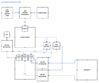
Here is where I am at right now --
1716217794958.png
Couple things.

1. I am not sure this is how the Bypass switches would be wired to exclude the inverter (or not). If you can double up the incoming single phase lines in the circuit box (and meet code) or if there is another methodology there. I'd need to check/verify.

2. Sol-Ark is just a named place holder for now it could be a different inverter just a proof of concept.

3. Based upon the information above sounds like I need to add a smaller inverter for the 50 amp loads. Not directly solar connected. Charge from the power in the panel, and then run on its own smaller battery set for that panel while the Genset fires up.

Any significant misses, thus far?
 
Last edited:
PV --> SolArk, make that two separate PV for separate SolArk.

Bypass AC into SolArk should be separate from PV DC.

Panel 1 & Panel 2 each fed by either bypass or by SolArk is correct.
However, additional ~ 100A panel fed by SolArk for backup loads would be convenient.

Plan to include "generator start" signal back from SolArk so it can request when (future) batteries get low. And ATS position switch feeding to SolArk. Couple empty conduit runs allow for addition. You'll have to find out how SolArk deals with generator vs. grid input.


A 200A breaker panel can have 200A main breaker interlocked with 125A backfed "generator" breaker; that is how I select between grid and my (smaller) inverter. Not clear that can be done with a 200A branch breaker. Square-D Homeline has a 200A branch breaker with 4 ganged handles that I think would work with sheet metal interlock. QO series, the 200A (4 pole) breaker has handle near middle, wouldn't be reached by UL listed interlock unless that was modified.

SolArk can pass through 200A but of course can't supply more than 1/4 as much (unless several in parallel.)
An external transfer switch can be used. I'm using interlocked breakers because economical and compact.


Does your utility have reasonable net-metering plan?
What is your cost for utility power? Some places have hydro so cheap that home PV costs just as much per kWh produced.
Other places, PV costs just 20% as much as utility, so of course adoption is popular, and utility got net metering terms changed to negate the benefits.
If you're not trying to run off batteries when grid is down, this is all about financial benefits.
 
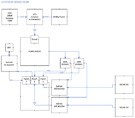
Updates. Thoughts?
1716221727731.png

Yes, there is a net-metering plan. I would need to dig into the specifics but I think that part is good.
Cost for utility power 19.66 per kWh, averaged.

The main driver for this is that even in my smaller house my average monthly power bill is ~$500.00. With the same relative power uses plus more sq. ft. I could easily see that going to ~700-800/month. Which overtime is just rediculous, honestly.

But you are correct, this is a financial incentive to decrease cost from the utility service. With the Gen being the true outage provider.
 
GT PV hardware can be had for about $1/W, maybe less these days (we see GStar PV panels from InXeption for $0.14/W + shipping.)
Amortized over 20 years, about $0.025/kWh.
Turnkey install about $3/W +/-, figure $0.10/kWh

Batteries like EG4 PowerPro $4k for 14kWh, 6000 cycles over 16 years, $0.05/kWh

So you can save money, if you utilize most of the power produced (net metering facilitates). With DIY PV, even if you waste 50% to 75% (so useful in hot areas for A/C even with no net metering.)


You still show one PV array branching to two inverters, would be multiple physical strings and no cross-connection between inverter PV inputs. Optionally share AC output and battery.

Would be nice to have PV going to SolArk 6k. Or have one of the 12k feed panel 3 all the time, manually also to the other panel(s).

Unless you have batteries on SolArk 12k (or consider 18kpv), little reason to have their output feeding panels. Can just have them backfeed "Bypass" as GT PV. or have them backfeed panel 1 & panel 2 (within 120% rule, e.g. use 225A panel, 200A main breaker, 70A backfed PV breaker.)
They do offer batteryless backup, which is completely limited to PV available at the moment.
Even 4x automotive starting batteries for 48V should help them provide starting surge to kick over a motor. PV direct is more limited.

As I mentioned earlier, wiring trough rather than conduit Tee gives you flexibility to rearrange wires later.
I have a couple 2" conduit from one panel to trough, and cut bigger to fit 3" conduit from my 200A panel.
Thank you! I updated the diagram below. Some of that was laziness on my end, but it's updated. :)

Questions ...

1 - What is the advantages of having a PV connect to the SolArk 6k, in pure curiosity terms? If the 12k is connected to Panel 1 for example wouldn't the net benefits of the solar make its way down to the 6k anyways?
Since, we are only really concerned about charging the batteries for crit loads in this particular use case.

2 - Need help understanding in lamens what you're indicating here (don't want to make any assumptions) -
"Unless you have batteries on SolArk 12k (or consider 18kpv), little reason to have their output feeding panels. Can just have them backfeed "Bypass" as GT PV. or have them backfeed panel 1 & panel 2 (within 120% rule, e.g. use 225A panel, 200A main breaker, 70A backfed PV breaker.)"

And yes, agreed on a centralized wiring solution. This is really just to get a more holistic feel for what we need to accomplish.

1716223344171.png
 
My two cents.

  1. If backup power is not a requirement, then hybrid inverters are not needed. Including them Hybrids will complicate the issue of making sure that your grid tied PV and Generator can not run at the same time.
  2. Other users here are correct when they say that the system must be designed to disallow that from happening.
  3. The simplest way to provide mutual exclusion is to attach your grid tied solar on the Utility side of the transfer switch. When the grid dies and the transfer switch is changed to the generator, the grid tied PV is automatically switched out of the active circuit.
  4. Microinverters would be the simplest way to achieve what you describe. Probably you should add a grid disconnect as the first item coming from the utility, then hook your combiner box to that feed through a fused disconnect.
  5. If you plan to eventually add backup capability, then you probably want a DC coupled system. In that case use a simple grid tied inverter instead of the microinverters. You can (in theory) AC couple micro inverters to Hybrid Inverters, but AC coupled is a pain in the neck to actually get working. I know, I have it. It took 1 1/2 years to get my system to actually produce power when off grid.
  6. If you go with hybrid inverters, the proper place for the bypass switches is before each panel. The center tap goes to the panel. One input goes to the output of the ATS. The other input goes to the output of the Hybrid inverter. Flipping the switch changes the source of the panels power.
  7. Depending of how you configure the rest of the system, the connection between the PV and the inverter will be high voltage DC which will go to the MTTP on the Hybrid for a DC coupled system. If your system is AC coupled it will go to the AC output on the Hybrid inverters or to the feed between the ATS and the grid if you are not using Hybrid Inverters.
  8. If you are going with a dual hybrid solution, you have some major design issues to figure out. First, part of what a hybrid inverter is built to do, is to manage separate feeds from a generator and a grid source. The inverter must treat these sources differently. It will know not to export power when it is fed through the Gen input. If you combine these two sources together, then you will have major issues properly configuring the system. It is probably better to keep the grid and gen sources separate until they get to the inverters. If there is power on the gen input to the inverter, you can use that to control a 4 pole 2NO and 2NC contactor. The PV is routed through the NC contacts and the gen is routed trough the NO contacts. So when you have gen power the Gen is connected and the PV is disconnected.
So my bottom line recommendation on this is that if you do not need backup power supplied from batteries, use some type of grid tied inverter. Then hook that grid tied inverter to the grid side of the ATS. The complications of adding Hybrid inverters into the system you are designing is considerable. Your ATS is designed to manage power from two sources, the grid and a generator. The problem is that this is also what a hybrid inverter is designed to do. So when these two sources are already combined together prior to reaching the Hybrid inverter, the Hybrid inverter does not know how to properly manage the input. So you really need to rethink whether you want an ATS or Hybrid inverters. You are going to have issues if you try to combine them together.
 
Last edited:
1 - What is the advantages of having a PV connect to the SolArk 6k, in pure curiosity terms? If the 12k is connected to Panel 1 for example wouldn't the net benefits of the solar make its way down to the 6k anyways?

As shown, PV is only available as grid input to 6k when grid is up.
With PV & battery on one inverter, it can power loads forever without grid. The more the merrier, so size for maximum backfeed, adjust battery charge rate to comfortable level, and you'll have power on somewhat overcast days with grid down.

A key to having power always on is "load shed", relays to disconnect larger loads when battery gets low.


Since, we are only really concerned about charging the batteries for crit loads in this particular use case.

2 - Need help understanding in lamens what you're indicating here (don't want to make any assumptions) -

"Unless you have batteries on SolArk 12k (or consider 18kpv), little reason to have their output feeding panels. Can just have them backfeed "Bypass" as GT PV. or have them backfeed panel 1 & panel 2 (within 120% rule, e.g. use 225A panel, 200A main breaker, 70A backfed PV breaker.)"

GT PV inverter like my Sunny Boy only backfeed grid when grid is up. They shut off when grid is down (or backfeed into my "island" grid formed by Sunny Island battery inverter.)

A hybrid like SolArk without battery can act like GT PV inverter, also backfeeding grid when grid is up.
If grid goes down, it can provide convenient power while sun shines, e.g. power refrigerators on its output, then shut off at night.
It could power larger loads like A/C and pumps as well, but starting surge has to come from PV. That's why I suggest a very small battery.

If you aren't trying to power anything with batteryless backup, then no reason to feed Panel 1 & Panel 2 through SolArk, just power direct from grid. Good to have the conduit available for future use if you add batteries. In the mean time, you're using an expensive feature-rich SolArk to do what Sunny Boy or a cheap Growatt GT PV inverter could do (as Whesinberg says). GT PV isn't mission critical; if it fails you just top getting credits on your bill but grid keeps the lights on.

If you have no immediate plans for battery, and you don't care about batteryless backup, save your money and install whatever GT PV inverter. If cheap enough, you can throw it away later and replace with a hybrid. But try to make PV string length & voltage, and any "RSD" Rapid Shut Down "MLPE" Module Level Power Electronics compatible with future plans.

I went with Sunny Boy GT PV and figured I'd eventually AC couple them to Sunny Island battery inverters. I finally did that when I got a liquidation bargain.

Today, many HF hybrids have the desired power and capabilities. SolArk, EG4 18kpv, Midnight The One, etc. so that route makes sense if you do intend to add batteries.

And yes, agreed on a centralized wiring solution. This is really just to get a more holistic feel for what we need to accomplish.

View attachment 216558

wheisenburg

mentioned issues with AC coupling (GT PV inverters feeding power to battery inverters).
We've heard of members having various problems doing that.

It works great with SMA Sunny Boy and Sunny Island. SMA invented grid-tied PV, and invented AC coupling. Anybody else, you pays you money and you takes you chances.

The hybrids have a feature that they can have larger PV array, supply AC to loads and/or grid and use additional PV power to charge battery. That can be better to right-size system when 120% rule limits you to 40A or 70A PV breaker. The hybrids can also be paralleled, or connected 3-phase, so you could have one large battery and one higher AC output. The ones with oversize 200A pass through mean no issue with timing and balancing of two smaller relays in parallel.

With a clean slate, you have more flexibility in how to wire things together.
 
My two cents.

  1. If backup power is not a requirement, then hybrid inverters are not needed. Including them Hybrids will complicate the issue of making sure that your grid tied PV and Generator can not run at the same time.
Understood
  1. Other users here are correct when they say that the system must be designed to disallow that from happening.
Ok
  1. The simplest way to provide mutual exclusion is to attach your grid tied solar on the Utility side of the transfer switch. When the grid dies and the transfer switch is changed to the generator, the grid tied PV is automatically switched out of the active circuit.
Given the discussion points above, is there a particular system you'd recommend here?
  1. Microinverters would be the simplest way to achieve what you describe. Probably you should add a grid disconnect as the first item coming from the utility, then hook your combiner box to that feed through a fused disconnect.
Do you install microinverters on each panel into a solar combiner and the fuse disconnect box on the utility side? Am I following?
  1. If you plan to eventually add backup capability, then you probably want a DC coupled system. In that case use a simple grid tied inverter instead of the microinverters. You can (in theory) AC couple micro inverters to Hybrid Inverters, but AC coupled is a pain in the neck to actually get working. I know, I have it. It took 1 1/2 years to get my system to actually produce power when off grid.
Fair. If I use the Microinverters above, can I still use the Sol-Ark 6k "idea" to cover my critical loads downstream? I will never add backup capacity to the 200-amp panels. The odds of doing this are likely 12%, but it's not a current consideration.
  1. If you go with hybrid inverters, the proper place for the bypass switches is before each panel. The center tap goes to the panel. One input goes to the output of the ATS. The other input goes to the output of the Hybrid inverter. Flipping the switch changes the source of the panels power.
Ok
  1. Depending of how you configure the rest of the system, the connection between the PV and the inverter will be high voltage DC which will go to the MTTP on the Hybrid for a DC coupled system. If your system is AC coupled it will go to the AC output on the Hybrid inverters or to the feed between the ATS and
Ok
  1. the grid if you are not using Hybrid Inverters.
  2. If you are going with a dual hybrid solution, you have some major design issues to figure out. First, part of what a hybrid inverter is built to do, is to manage separate feeds from a generator and a grid source. The inverter must treat these sources differently. It will know not to export power when it is fed through the Gen input. If you combine these two sources together, then you will have major issues properly configuring the system. It is probably better to keep the grid and gen sources separate until they get to the inverters. If there is power on the gen input to the inverter, you can use that to control a 4 pole 2NO and 2NC contactor. The PV is routed through the NC contacts and the gen is routed trough the NO contacts. So when you have gen power the Gen is connected and the PV is disconnected.
Ok
So my bottom line recommendation on this is that if you do not need backup power supplied from batteries, use some type of grid tied inverter. Then hook that grid tied inverter to the grid side of the ATS. The complications of adding Hybrid inverters into the system you are designing is considerable. Your ATS is designed to manage power from two sources, the grid and a generator. The problem is that this is also what a hybrid inverter is designed to do. So when these two sources are already combined together prior to reaching the Hybrid inverter, the Hybrid inverter does not know how to properly manage the input. So you really need to rethink whether you want an ATS or Hybrid inverters. You are going to have issues if you try to combine them together.
I am happy to explore a grid-tied inverter, barring my questions above. Because of the location of various panels and the need for generator power at those specific panels, I am not sure if I have an idealistic way to combine the generator power with the inverters to ditch the ATS switch, and still feed the power up to the pump house, for example.

So with that in mind. If I am following. Sounds like a grid-tied inverter (again recommendation on type?). And I am still curious about the 6k Sol-Ark consideration, again.

And thank you!
 
Microinverters like IQ7 and now with firmware update IQ8 can AC couple to a battery inverter.

I recommend string inverters or hybrids rather than microinverters. They are lower cost (although RSD requirement was probably created to erode that benefit), more reliable, more efficient, better match to large PV panels, can support PV strings of multiple orientations for more hours power generation.

Unless you really don't care about battery backup for future grid unreliability or malicious utility rates, I suggest planning system to support it.

I've always liked SMA and their older equipment, but the direction they are headed is HF inverter primarily for grid-tie with battery backup and wimpy starting surge as an afterthought.

SolArk is HF with good surge and great support, many happy users.

Midnight is the guys behind several decades of the most trusted equipment in the industry, so we are very interested in HF Rosie and The One. The One is aimed at same space as SolArk and EG4 18kpv, with all approvals for utility interconnection.
 
Okay, I am back!
Microinverters like IQ7 and now with firmware update IQ8 can AC couple to a battery inverter.

I recommend string inverters or hybrids rather than microinverters. They are lower cost (although RSD requirement was probably created to erode that benefit), more reliable, more efficient, better match to large PV panels, can support PV strings of multiple orientations for more hours power generation.
Ok
Unless you really don't care about battery backup for future grid unreliability or malicious utility rates, I suggest planning system to support it.
I tend to agree with making it a possibility if my mind were to ever change.
I've always liked SMA and their older equipment, but the direction they are headed is HF inverter primarily for grid-tie with battery backup and wimpy starting surge as an afterthought.

SolArk is HF with good surge and great support, many happy users.

Midnight is the guys behind several decades of the most trusted equipment in the industry, so we are very interested in HF Rosie and The One. The One is aimed at same space as SolArk and EG4 18kpv, with all approvals for utility interconnection.
Ok
......

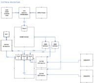
So based on my last rough draft -
1716305237490.png

What modifications need to be made to address the concerns that were made above with balancing the system?

I can add communication lines between the Sol-Ark inverters and the Genset easily enough when we put down the common trench with all of this stuff going back and forth between the two locations. But I cannot feed the generator power directly into the Inverter boxes as I still need to power the Pump House, and down.

It may be possible to wire in NC NO connections down stream to some kind of splitter box that sends the electrical current to the AC IN or GEN IN on the inverters depending upon whether the Generator is running, or not? That is a completely off the wall thought? And then the question about is it really a necessary need (or a mild concern).

Thanks.
 

diy solar

diy solar
Back
Top