diy solar

diy solar

Frequency shifting ports for EG4/Luxpower/Sol-Ark - not identical?

godawgs

New Member
Joined
Jul 22, 2020
Messages
39
Well, I waited a year for a split-phase inverter similar to the EG4 18K, Luxpower 12K, and Sol-Ark 15K that will support 80-400V batteries. It didn't happen, so I'll be pulling the trigger on a 48V system.

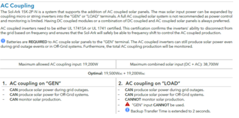
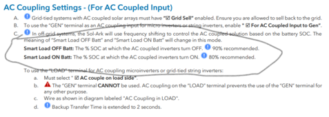
I wanted to get some first-hand feedback from those that have AC-coupled their on-grid inverters to any of these inverters. I've confirmed with Sol-Ark that frequency shifting for their systems occurs only on the GEN port, where AC coupling is supposed to take place. The LOAD port, however, does not experience any frequency shifting. Therefore any on-grid inverters tied to a service entrance panel, for example, will not adjust output in the case where the inverter is modulating AC-coupled power. I have 30kWp/24kWi of on-grid inverters, and (1) Sol-Ark 15K is limited to 19.2kW of AC coupling. Short of buying (2) of these inverters, this won't work. Additionally, the Sol-Ark frequency shifting is not pretty - basically on or off - with no gradient. I like Sol-Ark a lot. Their customer/technical support is second to none. But purchasing an extra unneeded inverter at their prices is not an efficient use of capital. Further, at least the Luxpower inverter specifies a gradient frequency shift up to the 62 hz level, versus the sudden shift that Sol-Ark inverters perform.

I cannot find anywhere on what port(s) the EG4 and Luxpower perform their frequency shifting. Since I have my on-grid inverters on the line side of my service entrance, it just needs to see a system-wide frequency shift to adjust power output. So I need the frequency shifting to be on the LOAD port. Does anyone have experience with this and can confirm with certainty where the frequency shifting takes place on the EG4 and Luxpower inverters?

Thanks!
 
Well, I waited a year for a split-phase inverter similar to the EG4 18K, Luxpower 12K, and Sol-Ark 15K that will support 80-400V batteries. It didn't happen, so I'll be pulling the trigger on a 48V system.

Growatt supports 400v batteries.

I wanted to get some first-hand feedback from those that have AC-coupled their on-grid inverters to any of these inverters. I've confirmed with Sol-Ark that frequency shifting for their systems occurs only on the GEN port, where AC coupling is supposed to take place. The LOAD port, however, does not experience any frequency shifting. Therefore any on-grid inverters tied to a service entrance panel, for example, will not adjust output in the case where the inverter is modulating AC-coupled power.

It shouldn't make a difference. All the ports will see the same frequency. It can't take 60.5hz from the Gen Port and send 60.0hz to the Load port.

1717189590108.png
I have 30kWp/24kWi of on-grid inverters, and (1) Sol-Ark 15K is limited to 19.2kW of AC coupling.

That is 100% true if you use the Gen Port (gen port limit is 19.2kW). I can't see why there is a limit on the Load Port. The SA can pass through 200A between the Grid and Load port. It shouldn't matter which direction.

Maybe there is a Grid Down issue. In that instance, tie the RSD for panels in excess of 19.2kW to the Grid. When the Grid goes down, those panels shut off.

Short of buying (2) of these inverters, this won't work. Additionally, the Sol-Ark frequency shifting is not pretty - basically on or off - with no gradient.

That might be related to the 19.2k AC PV limit when grid down. But it is really a AC PV <= DC PV so the SA can gracefully ramp down DC PV, and then simultaneously turn off AC PV, and fully turn back on DC PV. That is a grid down problem, and not a problem when the grid is up.

I like Sol-Ark a lot. Their customer/technical support is second to none. But purchasing an extra unneeded inverter at their prices is not an efficient use of capital.

What are you using for AC PV? If you use a Sol-Ark, it is a little more expensive, but then you can parallel the Sol-Arks, and get a lot of other benefits.
 
So you want to shift the frequency to 62 Hz to do what? What is the actual problem you're trying to solv

Growatt supports 400v batteries.


It shouldn't make a difference. All the ports will see the same frequency. It can't take 60.5hz from the Gen Port and send 60.0hz to the Load port.

View attachment 218942


That is 100% true if you use the Gen Port (gen port limit is 19.2kW). I can't see why there is a limit on the Load Port. The SA can pass through 200A between the Grid and Load port. It shouldn't matter which direction.

Maybe there is a Grid Down issue. In that instance, tie the RSD for panels in excess of 19.2kW to the Grid. When the Grid goes down, those panels shut off.


That might be related to the 19.2k AC PV limit when grid down. But it is really a AC PV <= DC PV so the SA can gracefully ramp down DC PV, and then simultaneously turn off AC PV, and fully turn back on DC PV. That is a grid down problem, and not a problem when the grid is up.


What are you using for AC PV? If you use a Sol-Ark, it is a little more expensive, but then you can parallel the Sol-Arks, and get a lot of other benefits.
@DIYrich - Thanks for the detailed response. Much appreciated.

1. If Growatt makes a hybrid, >12K, split-phase, frequency modulating, 200A utility bypass, 400V battery storage capable inverter - I am all eyes and ears.
2. I've been told this by 2 separate Sol-Ark technicians - the frequency change goes from 60.0 to 62.0 within a matter of a few seconds. There is no modulation in between. So there is no graceful ramp down of AC coupled inputs on the GEN port. They are either ON or OFF. At least that is what I was told. If so, this isn't ideal. And it's surprising to me, coming from a quality company like Sol-Ark
Screenshot 2024-05-31 203111.png
3. I agree that it doesn't make sense for the frequency on the AC-coupled GEN port to be different than the LOAD port. The on-grid inverters are synced with the GRID frequency. I would think that in Off-grid mode, the frequencies on both the GEN and LOAD ports would be the same. But maybe Sol-Ark does something different here? I also believe that frequency shifting doesn't take place unless you put the AC PV on the GEN port, but not 100% certain of this.
4. My AC PV are all SEDG systems. I like them. And I like that shading or panel issues aren't a concern because of the optimizers. I know that all of the hybrids work better with some DC PV, so planning to put ~4kWp stringed DC PV into it. But the largest source of power was intended to be the AC PV from my current systems. This was always my intention - the batteries would be used for backup only, thereby prologing lifetime.
5. I almost can't stand the thought of shutting down perfectly good power producers due to some hardware limitation in the inverter. I'd rather load dump into some heating elements than shut them down. Or even mine BTC, lol. By the time all of this is done, I will have at least 40kWp, mostly AC PV. In writing this, it's occurred to me that maybe I just need to go with a Sol-Ark 30k which does support high voltage batteries. I actually have 3 phase on my property. I don't use the 208V phase at all, and my AC PV is just split phase, so would have to investigate if the 30k would function correctly with just split-phase AC coupling.

In any case, the Growatt inverter sounds intriguing.
 
Last edited:
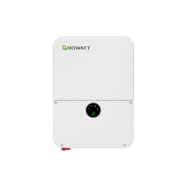
Largest growatt is 11.4kw

Has everything but isolation. For that you need:

I can see why SA is on/off with frequency shifting. There is no guarantee how gradual the ac pv responds. The ac pv could all blink off at 60.5 hz, so the SA just tells everything to turn off, and expects it all to go away. Easier than trying to watch how much goes away. Did it go away because of frequency shift. Or a cloud came by?

Too expensive to isolate the gen and load ports. Especially with the options available on the gen port. They all have the same frequency. My guess is that it will frequency shift the ac pv on load. Doesn't make sense not to.

I would max out dc pv with that much ac pv. The point is: if it has to turn off ac pv, you want as much dc pv available to buffer the switch.

Shutting off production isn't an inverter problem. The issue is the power needs to go somewhere. That is a system design problem. You have to provide a place to dump excess power. You can dump to the gen port.
Awesome, thanks! I just checked out the Growatt. I didn't see where it stated frequency shifting capability - AC coupling was supported, it's UL1741SA certified, so you'd think it would have it. If it supports non closed-loop BMS communication, I will investigate further. If it's proprietary battery packs or comm protocols only, then I would have to shut that idea down. I'd planned to use Orion's BMS'.

I would love for someone to confirm that the SA hybrid inverters frequency shift on the LOAD port too. I agree that it would be sensical, but purchasing one just to find out wouldn't be. Especially since SA themselves said that it was only on the GEN port.

Load dumping was what I'd planned if frequency shifting wasn't available. But relays for high-voltage batteries are really expensive, and I was planning to use the BMS' relays for that. Overall it's not ideal as more components = higher risk of system failure. As I said, I've got a 48s LFP battery back sitting in my workshop that I'd love not to have to break down. If a HV inverter is suitable, I'd just add another 48s string to make 96s, which should sit well within the Growatt's range.
 
Both of them frequency shift on the gen and load ports.
The benefit of the gen port is the ability to disconnect its relay, when frequency shifting is too slow. Which avoids damage from forced power, with nowhere to go.
 
2. I've been told this by 2 separate Sol-Ark technicians - the frequency change goes from 60.0 to 62.0 within a matter of a few seconds. There is no modulation in between. So there is no graceful ramp down of AC coupled inputs on the GEN port. They are either ON or OFF. At least that is what I was told. If so, this isn't ideal. And it's surprising to me, coming from a quality company like Sol-Ark

I think you have a (common) misunderstanding of how frequency shift works in an off-grid AC coupling system. Frequency shift is not intended for granular power ramping in an off-grid system. It's intended to be a more graceful way to turn off AC coupled power. The alternative is cutting the AC connection; this is worse b/c the inverters are probably not rated to do this a ton of times, and there is a long reconnect time mandated by 1741. The Frequency-Watts curve is nice and all, but it hides the response latency, which is allowed to be 1-2 seconds. And the curve is one of the 1741SA grid protection schemes. 1741SA does not care about AC coupling.

So why is it Sol-Ark's fault / egg on their face?

If you want super granular power ramping, you need a DC coupled system, or a AC coupled system with proprietary communications (EG Enphase), that allows better control than frequency-watts.

WRT wasting production, I am pretty sure large scale solar farms are willing to leave some on the table -- they use AC coupling and looser production / load matching, in exchange for simpler coordination.

Load dumping was what I'd planned if frequency shifting wasn't available.
You can just disconnect the AC strings. UL-listed 240VAC contactors/relays are a dime a dozen (not pricy, not hard to find).

As I said, I've got a 48s LFP battery back sitting in my workshop that I'd love not to have to break down. If a HV inverter is suitable, I'd just add another 48s string to make 96s, which should sit well within the Growatt's range.
You would need to source a 96V capable BMS, I don't believe those are commodities yet unlike the 48V BMS.

This was always my intention - the batteries would be used for backup only, thereby prologing lifetime.
Theoretically for many ESS cases the calendar wear will hit at the same time as daily cycle, so this isn't a super important concern.
 
I think you have a (common) misunderstanding of how frequency shift works in an off-grid AC coupling system. Frequency shift is not intended for granular power ramping in an off-grid system. It's intended to be a more graceful way to turn off AC coupled power. The alternative is cutting the AC connection; this is worse b/c the inverters are probably not rated to do this a ton of times, and there is a long reconnect time mandated by 1741. The Frequency-Watts curve is nice and all, but it hides the response latency, which is allowed to be 1-2 seconds. And the curve is one of the 1741SA grid protection schemes. 1741SA does not care about AC coupling.
Thanks, I'm aware of how frequency shifting works. I think I made it clear how much I like Sol-Ark in my OP. Sol-Ark's frequency shifting is effective an AC-coupled cut-off.
So why is it Sol-Ark's fault / egg on their face?

I don't fault Sol-Ark. Their AC-coupled solution just doesn't work for what I want.
If you want super granular power ramping, you need a DC coupled system, or a AC coupled system with proprietary communications (EG Enphase), that allows better control than frequency-watts.
Understood. And, of course. However, I already have a significant amount of capital invested in on-grid inverters that are productive. While movement to a fully DC coupled system may ultimately be the best solution, it would be foolish not to exploit the assets I already have.
WRT wasting production, I am pretty sure large scale solar farms are willing to leave some on the table -- they use AC coupling and looser production / load matching, in exchange for simpler coordination.
WRT to wasting production, energy is wasted all the time due to the unique requirements of load balancing large scale grids. I am not a large solar farm and can't pass on waste costs to customers nor build them into the electricity pricing.
You can just disconnect the AC strings. UL-listed 240VAC contactors/relays are a dime a dozen (not pricy, not hard to find).
Yes, 240V AC relays are cheap and readily available. I was referring to high-voltage DC programmable relays, DC-AC specifically, that would open the AC contact(s) when the HV battery reaches the setpoint. Again, this solution train is not even close to ideal and I wouldn't even hop on it unless there were no other choices, which there are.
You would need to source a 96V capable BMS, I don't believe those are commodities yet unlike the 48V BMS.
Orion (among others I'm sure) manufactures a 108-cell capable BMS that would work fine for a 96S LFP pack. The issue is there are no HV inverters with all of the requirements I seek.
Theoretically for many ESS cases the calendar wear will hit at the same time as daily cycle, so this isn't a super important concern.
 
Thanks, I'm aware of how frequency shifting works

I don't fault Sol-Ark. Their AC-coupled solution just doesn't work for what I want.
This isn't clear to me. If you accept that AC Coupling is a weak control interface, then it is inconsistent to believe that it is easy to achieve the control scheme that I think you want. Can you specify the requirements precisely? Sounds like you don't want to waste any production? (therer's probably a % that is OK?)

You also appear to be a little loosy-goosy wrt whether this is an on-grid use case or off-grid use case. I believe it is off-grid though upon reviewing several of your posts. I will refer back to this below (*)

I am skeptical that LuxPower does something useful with the gradient given the weak guarantees 1741SA compliance provides. And IMO you should be too unless somebody provides empirical measurement of the behavior.
WRT to wasting production, energy is wasted all the time due to the unique requirements of load balancing large scale grids. I am not a large solar farm and can't pass on waste costs to customers nor build them into the electricity pricing.
You'll find plenty of talk on this forum about how solar panels are cheap, just overpanel. The hard part is regulation - code compliant mount, whether you hit limit with your POCO.

I run computers privately and at scale in data centers, and in both places I throw in the towel instead of squeezing the utilization rock to the bitter end.
Again, this solution train is not even close to ideal and I wouldn't even hop on it unless there were no other choices, which there are.
I would suggest quantifying the difference between the "not even close to ideal" and the ideal, versus the implementation complexity of a multi-vendor system. I know I can't tune a control loop properly to achieve that, not being a control theory guy, or a power electronics guy (IE, so I can solve the problem at a different level).

So for instance, let's say you have a dump load that isn't the AC charger. And let's say it's a proportionally controllable heater that you can ramp smoothly. You will still need to be able to reliably how much excess there is. If you are on-grid (*), this is easier because you can implement a CT control loop to zero out the export, and any over-/under-shoot in the control loop is buffered by the grid. This is universal across many different power architectures. If you are off-grid, that is not possible. It is especially difficult with an AC coupled system. With a DC coupled solution, you still need API hooks into the MPPT to know how much excess power is being left on the table. In a hybrid, this is implemented with internal communications between the components.

Yes, 240V AC relays are cheap and readily available. I was referring to high-voltage DC programmable relays, DC-AC specifically, that would open the AC contact(s) when the HV battery reaches the setpoint. Again, this solution train is not even close to ideal and I wouldn't even hop on it unless there were no other choices, which there are.

I'm kind of confused. If you have BMS communications or a shunt, can't you achieve this with basic PLC and AC contactor? Have the PLC read the SoC setpoint via a data communications protocol. The exotic component in there is appropriate BMS/shunt that can handle HVDC battery and do counting to do SoC, but you probably need one anyway to be able to manage the battery properly.
 
This isn't clear to me. If you accept that AC Coupling is a weak control interface, then it is inconsistent to believe that it is easy to achieve the control scheme that I think you want. Can you specify the requirements precisely? Sounds like you don't want to waste any production? (therer's probably a % that is OK?)

I don't accept that AC coupling can't work as designed. Admittedly, the control response is less than ideal. It's slow. All of my SEDG inverters have fully adjustable parameters for controlling responses to frequency shifts. I've not read that it doesn't work. But the frequency shifting needs to perform on a gradient, not on/off. If done on a gradient, overall power control by the inverter is also less reliant on DC coupling. In any event, I planned to implement a fail-safe relay anyway in the event the AC power modulation failed, for whatever reason.
You also appear to be a little loosy-goosy wrt whether this is an on-grid use case or off-grid use case. I believe it is off-grid though upon reviewing several of your posts. I will refer back to this below (*)
I specified in the OP that this is a hybrid use case, so it's both on and off-grid. When the grid is up, the batteries are fully charged (well, 90% at peak), all unconsumed power is exported. The batteries are never cycled. No peak shaving, energy shifting, etc. If the grid goes down, well, you already know.

I am skeptical that LuxPower does something useful with the gradient given the weak guarantees 1741SA compliance provides. And IMO you should be too unless somebody provides empirical measurement of the behavior.

That was the point of my OP: Does anyone have any information on Luxpower's frequency shifting mechanism. The manual says it is graded, which is what I want. But I don't necessarily trust everything in an inverter's user manual.
You'll find plenty of talk on this forum about how solar panels are cheap, just overpanel. The hard part is regulation - code compliant mount, whether you hit limit with your POCO.

They are cheap. I am also oversized 20-30%. My POCO limit is 50kW. I have 3-phase, and the 15kVA transformers are on my property. So I will never achieve 50kW. Code compliancy is easy in Texas. Still, I'm compliant to CA regs. Because they are solid and safe.
I run computers privately and at scale in data centers, and in both places I throw in the towel instead of squeezing the utilization rock to the bitter end.

I agree. Spending 80% of your effort to achieve 20% better results isn't normally worth it.
I would suggest quantifying the difference between the "not even close to ideal" and the ideal, versus the implementation complexity of a multi-vendor system. I know I can't tune a control loop properly to achieve that, not being a control theory guy, or a power electronics guy (IE, so I can solve the problem at a different level).

Thanks. I have the various scenarios already vetted, having over a year to vet each of them. Controls aren't that challenging to me. But as any FMEA would dictate, the more controls, the more failure points. And any 'DIY' control system on a critical component at these power levels is unwise, which is why I am leaning towards accepting the 48V solution.
So for instance, let's say you have a dump load that isn't the AC charger. And let's say it's a proportionally controllable heater that you can ramp smoothly. You will still need to be able to reliably how much excess there is. If you are on-grid (*), this is easier because you can implement a CT control loop to zero out the export, and any over-/under-shoot in the control loop is buffered by the grid. This is universal across many different power architectures. If you are off-grid, that is not possible. It is especially difficult with an AC coupled system. With a DC coupled solution, you still need API hooks into the MPPT to know how much excess power is being left on the table. In a hybrid, this is implemented with internal communications between the components.

Any theorized load dump would key off of battery voltage and nothing else. And a scalable load dump would involve separate individual load dumps rather than a single one that is able to ramp up or down. But this is just a theory at this point. What is not theory is that I would rather have a bunch of Antminer S19s that turn on at different battery voltages than turn off an AC coupled system producing perfectly usable power. But I need frequency shifting as a safeguard in the event the load dump control scheme fails.
I'm kind of confused. If you have BMS communications or a shunt, can't you achieve this with basic PLC and AC contactor? Have the PLC read the SoC setpoint via a data communications protocol. The exotic component in there is appropriate BMS/shunt that can handle HVDC battery and do counting to do SoC, but you probably need one anyway to be able to manage the battery properly.

Yes, that is precisely the issue with HV batteries. There are very few resources for them right now. For 48V, everything you wrote is definitely doable, and very easily.
 
I've confirmed with Sol-Ark that frequency shifting for their systems occurs only on the GEN port, where AC coupling is supposed to take place. The LOAD port, however, does not experience any frequency shifting. Therefore any on-grid inverters tied to a service entrance panel, for example, will not adjust output in the case where the inverter is modulating AC-coupled power.
When the grid is passing through any hybrid inverter there is no frequency shift because the grid frequency cannot be shifted and different parts of an inverter cannot operate at different frequencies. Freguency shift is only effective when off grid or when the grid has dropped. In my case when the grid is up there is no need to modulate the output of my micros because any production beyond the loads is simply exported. If your situation is a non export case, adding micros may not be optimal unless you can program the micros for non export. That is more complicated in terms of placement of CTs and may require consumption CTs to make it work effectively.
 
When the grid is passing through any hybrid inverter there is no frequency shift because the grid frequency cannot be shifted and different parts of an inverter cannot operate at different frequencies. Freguency shift is only effective when off grid or when the grid has dropped. In my case when the grid is up there is no need to modulate the output of my micros because any production beyond the loads is simply exported. If your situation is a non export case, adding micros may not be optimal unless you can program the micros for non export. That is more complicated in terms of placement of CTs and may require consumption CTs to make it work effectively.
Yes, that's correct. I am referring to the scenario in which the hybrid is producing power and the grid is down. An AC coupled scheme would require a mechanism for power modulation in a grid down event. I never thought about using CTs as control inputs, though I'm not sure it's the most reliable way as the battery SOC or voltage isn't a function of production current.
 
I am referring to the scenario in which the hybrid is producing power and the grid is down.
Each algorithm is different in each grid forming inverter in terms of how it applies frequency shift. I am of the opinion that the reason SolArk and others use the GEN port for AC coupling is because they can open the GEN port relay much quicker than using frequency shift. That way they can avoid damage when load drops and the AC coupled inverter(s) cannot ramp down quick enough because of the latency built into the specs of the AC coupled inverter(s). That latency is built into any Grid tied inverter following CA Rule 21 and the equivalent UL spec and cannot typically be changed easily. There is a lot of discussion on this forum of this topic if you need more detail?
 
Last edited:
Each algorithm is different in terms of how it applies frequency shift. I am of the opinion that the reason SolArk and others use the GEN port for AC coupling is because they can open the GEN port relay much quicker than using frequency shift. That way they can avoid damage when load drops and the AC coupled inverter(s)
I agree. The safest AC cutoff is exactly that, only capable by physical disconnection. But really, it's a little telling of their confidence in their frequency shifting system. I'm not an EE, but I'm guessing it's harder than it is easier.
 
I never thought about using CTs as control inputs, though I'm not sure it's the most reliable way as the battery SOC or voltage isn't a function of production current.
I only mentioned CTs in the context of programming micros for non export. It is not relevant in a grid down scenario. Yes, the algorithm in some hybrids must use battery SOC as an input to know how much cushion there is if loads drop. The battery SOC would give them an idea about how much of the AC coupled output could be shifted to battery charging if there was a sudden drop of other loads. That would require a fairly acurate SOC estimate, of which I have found the SolArk estimate of SOC to not be reliable. This was confirmed when I lost communication with my batteries. I was able to independently poll my pack for SOC and it was significantly different than what the SolArk was reporting.
 
Last edited:
I don't accept that AC coupling can't work as designed. Admittedly, the control response is less than ideal. It's slow. All of my SEDG inverters have fully adjustable parameters for controlling responses to frequency shifts. I've not read that it doesn't work. But the frequency shifting needs to perform on a gradient, not on/off. If done on a gradient, overall power control by the inverter is also less reliant on DC coupling. In any event, I planned to implement a fail-safe relay anyway in the event the AC power modulation failed, for whatever reason.
I guess at this point it's my off-the-clock analysis that 1741SA is not suitable for smooth control

The inputs to my analysis
- 1741SA is for grid stability. Grid stability does not require fast response from GTIs. Indeed, IQ8s (which are hybrid microinverters capable of batteryless operation to serve loads) are lauded for fast response compared to IQ7s

Page 197 of my POCO regulations says 5 seconds, which would be tough to work with:
1717384414034.png
Meta:
- Regular time to ramp back up without 1741SA is like 5+ min. Dropping this from 5+ min to seconds is already a good enough win
- I don't actually think the amount of time proportional F-W will be beneficial is that high. Suppose you have fully elastic dump load (can ramp up and down, mining is like this). You can a binary-only F-W inverter from ever turning off, by absorbing the full microinverter AC output.

In fact, you can implement a control scheme to drive the battery to any level you want.

(This is completely under your control)

- Now, suppose you do have proportional F-W. If it ramps down, that means your battery is no longer able to absorb all output power. You're already losing production in this case, and should have turned on your elastic dump load.

Now, when does frequency shift need to ramp down? It is above the SoC cutoff where the inverter / BMS needs to taper SoC. Let's say it's 80%. Then the ramping frequency shift is only relevant between 80-100% SoC.

You could design the battery with 20% reserve (add more capacity to achieve), this would also extend the life of the battery

(This is completely under your control)

(What is not under your control, unless you have relationship with a power electronics team to build it for you, is to create a product with proportional F-W if it doesn't already exist)

Any theorized load dump would key off of battery voltage and nothing else. And a scalable load dump would involve separate individual load dumps rather than a single one that is able to ramp up or down. But this is just a theory at this point. What is not theory is that I would rather have a bunch of Antminer S19s that turn on at different battery voltages than turn off an AC coupled system producing perfectly usable power. But I need frequency shifting as a safeguard in the event the load dump control scheme fails.
Why would you key off battery voltage? Battery voltage will vary as load changes due to the internal resistance. SoC (implemented by coloumb counting and periodically re-calibrated) is more robust.

Yes, that's correct. I am referring to the scenario in which the hybrid is producing power and the grid is down. An AC coupled scheme would require a mechanism for power modulation in a grid down event. I never thought about using CTs as control inputs, though I'm not sure it's the most reliable way as the battery SOC or voltage isn't a function of production current.

Originally, I thought CT at the connection to grid for control input is for on-grid use. As I said you don't need to be a EE or control wizard to make something work with this... you can write some python script and it'll be safe, just might be sub-optimal.

Thinking now, I think you can also put CTs in a couple accessible places, IE the microinverter feeder and the loads served from the inverter. By doing math you can see how much is going to the inverter.
 
I only mentioned CTs in the context of programming micros for non export. It is not relevant in a grid down scenario. Yes, the algorithm in some hybrids must use battery SOC as an input to know how much cushion there is if loads drop. The battery SOC would give them an idea about how much of the AC coupled output could be shifted to battery charging if there was a sudden drop of other loads.
I guess at this point it's my off-the-clock analysis that 1741SA is not suitable for smooth control

The inputs to my analysis
- 1741SA is for grid stability. Grid stability does not require fast response from GTIs. Indeed, IQ8s (which are hybrid microinverters capable of batteryless operation to serve loads) are lauded for fast response compared to IQ7s

Page 197 of my POCO regulations says 5 seconds, which would be tough to work with:
View attachment 219308
Meta:
- Regular time to ramp back up without 1741SA is like 5+ min. Dropping this from 5+ min to seconds is already a good enough win
- I don't actually think the amount of time proportional F-W will be beneficial is that high. Suppose you have fully elastic dump load (can ramp up and down, mining is like this). You can a binary-only F-W inverter from ever turning off, by absorbing the full microinverter AC output.

5 seconds is acceptable to me. A digital on/off is not. While I'm aware of the challenges of precisely controlling frequency during production, it is very possible. Luxpower's publications display a linear response in the derating, which is what I seek. However, what's published and actuality are often different. The single factor preventing me from purchasing an SA inverter today is this limitation in their AC couple control.
In fact, you can implement a control scheme to drive the battery to any level you want.

(This is completely under your control)

- Now, suppose you do have proportional F-W. If it ramps down, that means your battery is no longer able to absorb all output power. You're already losing production in this case, and should have turned on your elastic dump load.

There is no system I know of that will be able to achieve 100% utilization of full production capacity based on acceptable safety margins. That I understand.
Now, when does frequency shift need to ramp down? It is above the SoC cutoff where the inverter / BMS needs to taper SoC. Let's say it's 80%. Then the ramping frequency shift is only relevant between 80-100% SoC.
Correct.
You could design the battery with 20% reserve (add more capacity to achieve), this would also extend the life of the battery
An answer in many cases is larger batteries. But you need enough production too. In any grid-down scenario, my system would have to sustain itself indefinitely and with zero changes to consumption. This means over-storage wouldn't suffice alone. With a large enough production capacity, many cloudy days aren't a problem. A larger battery pack would be largely ineffective, since production may only be sufficient for consumption + storage of excess consumption = 24 hour power requirements. You are likely fully aware of the significant difference in power production on cloudy days. Suppose there are 2 weeks of cloudy weather? I'd rather double my production versus double my storage capacity. Financially, it was also lower cost to increase production versus increase storage. These days, storage costs have come way down, so maybe it's not so clear-cut. All of this, however, requires very good utilization of production capacity - and AC coupling control is key. One might ask if I have so much production capacity, why not just go fully off-grid? The reason is that there are more issues managing an off-grid system then a hybrid one - most notably battery degradation and lifetime. While they are cheaper now, they are still not something you consider as a consumable cost.
(This is completely under your control)

(What is not under your control, unless you have relationship with a power electronics team to build it for you, is to create a product with proportional F-W if it doesn't already exist)


Why would you key off battery voltage? Battery voltage will vary as load changes due to the internal resistance. SoC (implemented by coloumb counting and periodically re-calibrated) is more robust.
Yes, SOC is the metric used for virtually all control systems. As someone who's built LiPO and LFP packs for 15 years and run many different types of machines off of them, I just prefer voltage. Build your battery pack large enough, and voltage drops on loads are very small. LFP packs are even simpler to use voltage as a guide. A 12V pack will sit at 12.8V forever. But when it starts dropping, you know you are in your final 20% power remaining. There's no need to recalibrate SOC as the pack lifetime increases and Qmax decrease. Voltage will tell you.
Originally, I thought CT at the connection to grid for control input is for on-grid use. As I said you don't need to be a EE or control wizard to make something work with this... you can write some python script and it'll be safe, just might be sub-optimal.

Thinking now, I think you can also put CTs in a couple accessible places, IE the microinverter feeder and the loads served from the inverter. By doing math you can see how much is going to the inverter.
 
I'm sorry I haven't read the entire thread because I'm short on time, but have you looked at the SolArk 30k and 60k? It sounds like it checks all your boxes, including 150v-500v battery input, and you don't need more than 1.

 
Meta: Not sure why you aren't engaging with the math and the graphs... Going to have to snooze this thread for a while since it's not a super engaging one for me.

5 seconds is acceptable to me. A digital on/off is not.
Your opinion matters, but not as much as the opinion of physics. 5 seconds may not be acceptable for the control loop and voltage rise rate that the microinverter will create when on an imbalanced microgrid. And both the 5 seconds and the voltage rise will vary depending on the grid tie inverter that you have. So when a company says they can stably manage a microgrid with F-W throttling, then I ask, what GTIs was it qualified with? Or, if it is universally compatible, what is the secret sauce? Are you expecting the BMS to absorb a burst? Cut off AC relay if the BMS cuts charging path?

(Oops you have SEDG - just text/replace everything with SEDG)
While I'm aware of the challenges of precisely controlling frequency during production, it is very possible. Luxpower's publications display a linear response in the derating, which is what I seek. However, what's published and actuality are often different. The single factor preventing me from purchasing an SA inverter today is this limitation in their AC couple control.
Can you share the link with the linear response?

An answer in many cases is larger batteries. But you need enough production too. ...
Yes, this paragraph makes sense but that's not the goal of the oversizing. It's to keep the system able to absorb AC power at full power.

Suppose you need storage size X with perfect AC coupling, and you have zero throttling in that system, and satisfy annual energy storage requirements. It can be proven (with basic algebra proof) that you can have a system of 1/80% * X with imperfect AC coupling, that still has zero throttling and satisfies annual energy storage requirements.

But when it starts dropping, you know you are in your final 20% power remaining.
But for AC coupling cut-off it is 80% that matters. What does the voltage curve look like at this regime?
 
I'm sorry I haven't read the entire thread because I'm short on time, but have you looked at the SolArk 30k and 60k? It sounds like it checks all your boxes, including 150v-500v battery input, and you don't need more than 1.
Converting the 3-phase 208v output of the 30k to split phase 120v/240v may be a challenge.
 
I'm sorry I haven't read the entire thread because I'm short on time, but have you looked at the SolArk 30k and 60k? It sounds like it checks all your boxes, including 150v-500v battery input, and you don't need more than 1.

This thread is long, lol, so don't blame you. Yes, the 30K does check all of the boxes and indeed may be the direction I ultimately go. It is a 3-phase system, so need to verify a few other items. The AC coupling mechanism is the same as the 15K, as far as I know, so I'm not a fan of it. But it's not a show-stopper. A key requirement is that the 30K can work with open-loop BMS communication and not just closed-loop, as it specifies in the user manual. I'd also need to double up my 43kWH battery pack, which would be no small cost. I don't need 96kWH of storage, but I guess more is not necessarily bad. Thanks for the recommendation.
 
I think you have a (common) misunderstanding of how frequency shift works in an off-grid AC coupling system. Frequency shift is not intended for granular power ramping in an off-grid system. It's intended to be a more graceful way to turn off AC coupled power. The alternative is cutting the AC connection; this is worse b/c the inverters are probably not rated to do this a ton of times, and there is a long reconnect time mandated by 1741. The Frequency-Watts curve is nice and all, but it hides the response latency, which is allowed to be 1-2 seconds. And the curve is one of the 1741SA grid protection schemes. 1741SA does not care about AC coupling.
If you want super granular power ramping, you need a DC coupled system, or a AC coupled system with proprietary communications (EG Enphase), that allows better control than frequency-watts.
I guess you haven't seen a Victron/Fronius AC coupled system operating, have you?

In my personal system the Victrons have some pretty good control of the Fronius via frequency shift! (I'm off grid with zero DC coupled pv.) Of course the Fronius is configured to MG60, which tells it that it's off-grid (MicroGrid 60Hz) and adjusts some settings accordingly. But it is definitely possible to do a really nice job of gradual/granular curtailment via frequency shift!

In a grid-tied situation though, the GT inverters (SEDG in this case) do need to be configured for grid-interactive function, so you probably lose a little bit somewhere there. Likely you end up with a little more "laggy" control on ramp-up, but I would expect ramp-down to be totally possible to be pretty quick!

To OP: @godawgs Frequency on gen port and load terminals have no choice but to be "locked" as gen port is essentially just a contactor-controlled connection to the common AC bus (directly connected to load terminals). The reason for the limitations on how much PV can be AC coupled comes down to how much power the Sol-Ark can actually push to the batteries. At 275A you end up ~12kW, so going too much over that in AC coupled PV connection runs a risk of toasting the DC-DC Hi-Low/Low-Hi converter between battery and High Voltage DC bus in the inverter. The 200A passthrough of the 15K would allow for much more "passthrough" AC coupled PV. But in a grid-down scenario, if your loads are very low the only place left to push the PV power is to the batteries, and the only path there is through that 275A DC-DC.
 

diy solar

diy solar
Back
Top