You are using an out of date browser. It may not display this or other websites correctly.
You should upgrade or use an alternative browser.
You should upgrade or use an alternative browser.
JK-BMS-CAN with new Cut-Off Charging Logic (open-source)
- Thread starter Sleeper85
- Start date
Great job on multi-bms version. Thank you all on your hard work and time spent on this.
Just connected my Growatt SPF 5000 ES with my two DIY 16kWh batteries with JK PB series BMSes using BLE connections from AtomS3 with CAN Unit module - had to change gpio pins in yaml. Working good.
My questions are:
1) how do we control absorption time and float time? It is controlled automatically? Even if Auto Current and auto voltage buttons are off? Is the timeout option responsible for this?
2) when Force Bulk button is working? Tried right after Bulk phase - do not working, tried at 53,6V - do not working. Should I raise Rebulk value first than turn on Force Bulk?
EDIT: tried raising rebulk value than used force Bulk button, status changed to Bulk/Force bulk but inverter did not started to charge. Looks like this is not working for Growatt SPF 5000 using Pylon 1.2 protocol?
EDIT2: setting rebulk voltage and restarting ESP is the way to do rebulk. Looks like force bulk button is not working as expected. After turning it on and back off and on again it stays on at some point not allowing to turn it off. I know it's a beta that's why I post my observations
Last edited:
Hello, I recently buyed a JK BMS PB2A16S20P, Hardware version V15.XA, running V15.10 firmware and have issues compiling the code for ESP32 - C3 board or for standard ESP32. I have copied packages folder as well as secrets.yaml and i get the following error:In addition to the main YAML, you must have the packages folder as well as secrets.yaml (with your wifi credentials) in order to compile.
from src/main.cpp:3:
src/esphome/components/jk_rs485_sniffer/binary_output.h:18:7: error: redefinition of 'class esphome:
class BinaryOutput {
^~~~~~~~~~~~
In file included from src/esphome/components/binary/light/binary_light_output.h:4,
from src/esphome.h:15,
from src/main.cpp:3:
src/esphome/components/output/binary_output.h:18:7: note: previous definition of 'class esphome:
class BinaryOutput {
^~~~~~~~~~~~
Generating LD script .pioenvs/smartbms/memory.ld
Compiling .pioenvs/smartbms/app_trace/app_trace.o
*** [.pioenvs/smartbms/src/main.o] Error 1
========================= [FAILED] Took 607.51 seconds =========================
I have created a new board file for C3 board, and i cannot find what is the issue for not managing to compile.
The content for C3 board is as follows:
# Updated : 2024.05.19
# Version : 1.1
# GitHub : https://github.com/Sleeper85/esphome-jk-bms-can
esp32:
board: esp32-c3-devkitm-1
framework:
type: esp-idf
uart:
# UART 1
- id: uart_esp_1
tx_pin: 21
rx_pin: 20
baud_rate: 115200
rx_buffer_size: 384
canbus:
# CANBUS NODE 1
- platform: esp32_can
id: canbus_node1
tx_pin: 9
rx_pin: 8
can_id: 1
bit_rate: 500kbps
output:
# ESP LED
- platform: gpio
pin: 2
id: esp_led
inverted: true
light:
# ESP Light
- platform: binary
output: esp_led
id: esp_light
name: "${name} On board light"
internal: true
C3 has no onboard led but i will attach one on GPIO2 if it will manage to compile and run successfully.
If i choose board type esp32-s3 the code is compiling successfully but obviously it cannot be flashed to C3 board.
Any ideas?
chaosnature
New Member
- Joined
- Sep 15, 2022
- Messages
- 520
@virus100bHello, I recently buyed a JK BMS PB2A16S20P, Hardware version V15.XA, running V15.10 firmware and have issues compiling the code for ESP32 - C3 board or for standard ESP32. I have copied packages folder as well as secrets.yaml and i get the following error:
from src/main.cpp:3:
src/esphome/components/jk_rs485_sniffer/binary_output.h:18:7: error: redefinition of 'class esphome:utput::BinaryOutput'
class BinaryOutput {
^~~~~~~~~~~~
In file included from src/esphome/components/binary/light/binary_light_output.h:4,
from src/esphome.h:15,
from src/main.cpp:3:
src/esphome/components/output/binary_output.h:18:7: note: previous definition of 'class esphome:utput::BinaryOutput'
class BinaryOutput {
^~~~~~~~~~~~
Generating LD script .pioenvs/smartbms/memory.ld
Compiling .pioenvs/smartbms/app_trace/app_trace.o
*** [.pioenvs/smartbms/src/main.o] Error 1
========================= [FAILED] Took 607.51 seconds =========================
I have created a new board file for C3 board, and i cannot find what is the issue for not managing to compile.
The content for C3 board is as follows:
# Updated : 2024.05.19
# Version : 1.1
# GitHub : https://github.com/Sleeper85/esphome-jk-bms-can
esp32:
board: esp32-c3-devkitm-1
framework:
type: esp-idf
uart:
# UART 1
- id: uart_esp_1
tx_pin: 21
rx_pin: 20
baud_rate: 115200
rx_buffer_size: 384
canbus:
# CANBUS NODE 1
- platform: esp32_can
id: canbus_node1
tx_pin: 9
rx_pin: 8
can_id: 1
bit_rate: 500kbps
output:
# ESP LED
- platform: gpio
pin: 2
id: esp_led
inverted: true
light:
# ESP Light
- platform: binary
output: esp_led
id: esp_light
name: "${name} On board light"
internal: true
C3 has no onboard led but i will attach one on GPIO2 if it will manage to compile and run successfully.
If i choose board type esp32-s3 the code is compiling successfully but obviously it cannot be flashed to C3 board.
Any ideas?
Check and try to update your Esphome to
I was having issues and a non-intuitive error messages until I updated by running the below command (using Windows Cmd):
pip3 install esphome==2024.5.0
Also, update pip if you choose to use Windows.
I see you are running an even older version (2024.05.19) than I was running
hope that helps
chaosnature
New Member
- Joined
- Sep 15, 2022
- Messages
- 520
I will release a youtube on how to flash on Windows - it's a little tricky especially if you have a complex network like mine.
But very few steps....
But very few steps....
chaosnature
New Member
- Joined
- Sep 15, 2022
- Messages
- 520
@Sleeper85
One Question.
Do we still have to Set Protocol to SMA for Solis inverter as with the Old config?
Or are we back to using Pylon+ again as normal ?
One Question.
Do we still have to Set Protocol to SMA for Solis inverter as with the Old config?
Or are we back to using Pylon+ again as normal ?
MrPablo
Solar Enthusiast
You can use either Pylon or SMA.@Sleeper85
One Question.
Do we still have to Set Protocol to SMA for Solis inverter as with the Old config?
Or are we back to using Pylon+ again as normal ?
I recommend SMA for the Solis inverter, mainly because Solis apply some Pylontech specific logic for the pylon protocol.
That logic tends to affect how BMS voltage is used, plus prevents (from what I've seen) recharging until the SOC drops to 97%.
Of course, this is likely very dependent on inverter firmware.
chaosnature
New Member
- Joined
- Sep 15, 2022
- Messages
- 520
I will release a youtube on how to flash on Windows - it's a little tricky especially if you have a complex network like mine.
But very few steps....
@chaosnature
INFO ESPHome 2024.5.4
INFO Reading configuration /config/esphome/jk-inverter.yaml...
INFO Updating https://github.com/txubelaxu/esphome-jk-bms.git@main
INFO Detected timezone 'Europe/Bucharest'
INFO Generating C++ source...
INFO Compiling app...
Processing smartbms (board: esp32-s3-devkitc-1; framework: espidf; platform: platformio/espressif32@5.4.0)
--------------------------------------------------------------------------------
HARDWARE: ESP32S3 240MHz, 320KB RAM, 8MB Flash
- framework-espidf @ 3.40407.0 (4.4.7)
- tool-cmake @ 3.16.4
- tool-ninja @ 1.7.1
- toolchain-esp32ulp @ 2.35.0-20220830
- toolchain-riscv32-esp @ 8.4.0+2021r2-patch5
- toolchain-xtensa-esp32s3 @ 8.4.0+2021r2-patch5
Reading CMake configuration...
No dependencies
Compiling .pioenvs/smartbms/src/main.o
Archiving .pioenvs/smartbms/esp-idf/asio/libasio.a
Compiling .pioenvs/smartbms/bootloader_support/src/bootloader_common.o
Compiling .pioenvs/smartbms/bootloader_support/src/bootloader_common_loader.o
Compiling .pioenvs/smartbms/bootloader_support/src/bootloader_clock_init.o
Compiling .pioenvs/smartbms/bootloader_support/src/bootloader_flash.o
Compiling .pioenvs/smartbms/bootloader_support/src/bootloader_mem.o
Compiling .pioenvs/smartbms/bootloader_support/src/bootloader_random.o
Compiling .pioenvs/smartbms/bootloader_support/src/bootloader_random_esp32s3.o
In file included from src/esphome/components/jk_rs485_sniffer/jk_rs485_sniffer.h:6,
from src/esphome/components/jk_rs485_bms/jk_rs485_bms.h:8,
from src/esphome.h:32,
from src/main.cpp:3:
src/esphome/components/jk_rs485_sniffer/binary_output.h:18:7: error: redefinition of 'class esphome: utput::BinaryOutput'
class BinaryOutput {
^~~~~~~~~~~~
In file included from src/esphome/components/binary/light/binary_light_output.h:4,
from src/esphome.h:15,
from src/main.cpp:3:
src/esphome/components/output/binary_output.h:18:7: note: previous definition of 'class esphome: utput::BinaryOutput'
class BinaryOutput {
^~~~~~~~~~~~
Compiling .pioenvs/smartbms/bootloader_support/src/bootloader_utility.o
Compiling .pioenvs/smartbms/bootloader_support/src/esp_image_format.o
Compiling .pioenvs/smartbms/bootloader_support/src/flash_encrypt.o
Compiling .pioenvs/smartbms/bootloader_support/src/secure_boot.o
Compiling .pioenvs/smartbms/bootloader_support/src/flash_partitions.o
Compiling .pioenvs/smartbms/bootloader_support/src/flash_qio_mode.o
Compiling .pioenvs/smartbms/bootloader_support/src/bootloader_flash_config_esp32s3.o
Compiling .pioenvs/smartbms/bootloader_support/src/bootloader_efuse.o
Compiling .pioenvs/smartbms/bootloader_support/src/idf/bootloader_sha.o
Archiving .pioenvs/smartbms/esp-idf/bootloader_support/libbootloader_support.a
Compiling .pioenvs/smartbms/cbor/tinycbor/src/cborencoder_close_container_checked.o
Compiling .pioenvs/smartbms/cbor/tinycbor/src/cborencoder.o
Compiling .pioenvs/smartbms/cbor/tinycbor/src/cborerrorstrings.o
Compiling .pioenvs/smartbms/cbor/tinycbor/src/cborparser_dup_string.o
Compiling .pioenvs/smartbms/cbor/tinycbor/src/cborparser.o
Compiling .pioenvs/smartbms/cbor/tinycbor/src/cborpretty_stdio.o
Compiling .pioenvs/smartbms/cbor/tinycbor/src/cborpretty.o
*** [.pioenvs/smartbms/src/main.o] Error 1
========================= [FAILED] Took 46.05 seconds =========================
I have updated the Esphome. I am using Esphome under Home assistant. I am running last version. See below the log:@virus100b
Check and try to update your Esphome to
I was having issues and a non-intuitive error messages until I updated by running the below command (using Windows Cmd):
pip3 install esphome==2024.5.0
Also, update pip if you choose to use Windows.
I see you are running an even older version (2024.05.19) than I was running
hope that helps
INFO ESPHome 2024.5.4
INFO Reading configuration /config/esphome/jk-inverter.yaml...
INFO Updating https://github.com/txubelaxu/esphome-jk-bms.git@main
INFO Detected timezone 'Europe/Bucharest'
INFO Generating C++ source...
INFO Compiling app...
Processing smartbms (board: esp32-s3-devkitc-1; framework: espidf; platform: platformio/espressif32@5.4.0)
--------------------------------------------------------------------------------
HARDWARE: ESP32S3 240MHz, 320KB RAM, 8MB Flash
- framework-espidf @ 3.40407.0 (4.4.7)
- tool-cmake @ 3.16.4
- tool-ninja @ 1.7.1
- toolchain-esp32ulp @ 2.35.0-20220830
- toolchain-riscv32-esp @ 8.4.0+2021r2-patch5
- toolchain-xtensa-esp32s3 @ 8.4.0+2021r2-patch5
Reading CMake configuration...
No dependencies
Compiling .pioenvs/smartbms/src/main.o
Archiving .pioenvs/smartbms/esp-idf/asio/libasio.a
Compiling .pioenvs/smartbms/bootloader_support/src/bootloader_common.o
Compiling .pioenvs/smartbms/bootloader_support/src/bootloader_common_loader.o
Compiling .pioenvs/smartbms/bootloader_support/src/bootloader_clock_init.o
Compiling .pioenvs/smartbms/bootloader_support/src/bootloader_flash.o
Compiling .pioenvs/smartbms/bootloader_support/src/bootloader_mem.o
Compiling .pioenvs/smartbms/bootloader_support/src/bootloader_random.o
Compiling .pioenvs/smartbms/bootloader_support/src/bootloader_random_esp32s3.o
In file included from src/esphome/components/jk_rs485_sniffer/jk_rs485_sniffer.h:6,
from src/esphome/components/jk_rs485_bms/jk_rs485_bms.h:8,
from src/esphome.h:32,
from src/main.cpp:3:
src/esphome/components/jk_rs485_sniffer/binary_output.h:18:7: error: redefinition of 'class esphome:
class BinaryOutput {
^~~~~~~~~~~~
In file included from src/esphome/components/binary/light/binary_light_output.h:4,
from src/esphome.h:15,
from src/main.cpp:3:
src/esphome/components/output/binary_output.h:18:7: note: previous definition of 'class esphome:
class BinaryOutput {
^~~~~~~~~~~~
Compiling .pioenvs/smartbms/bootloader_support/src/bootloader_utility.o
Compiling .pioenvs/smartbms/bootloader_support/src/esp_image_format.o
Compiling .pioenvs/smartbms/bootloader_support/src/flash_encrypt.o
Compiling .pioenvs/smartbms/bootloader_support/src/secure_boot.o
Compiling .pioenvs/smartbms/bootloader_support/src/flash_partitions.o
Compiling .pioenvs/smartbms/bootloader_support/src/flash_qio_mode.o
Compiling .pioenvs/smartbms/bootloader_support/src/bootloader_flash_config_esp32s3.o
Compiling .pioenvs/smartbms/bootloader_support/src/bootloader_efuse.o
Compiling .pioenvs/smartbms/bootloader_support/src/idf/bootloader_sha.o
Archiving .pioenvs/smartbms/esp-idf/bootloader_support/libbootloader_support.a
Compiling .pioenvs/smartbms/cbor/tinycbor/src/cborencoder_close_container_checked.o
Compiling .pioenvs/smartbms/cbor/tinycbor/src/cborencoder.o
Compiling .pioenvs/smartbms/cbor/tinycbor/src/cborerrorstrings.o
Compiling .pioenvs/smartbms/cbor/tinycbor/src/cborparser_dup_string.o
Compiling .pioenvs/smartbms/cbor/tinycbor/src/cborparser.o
Compiling .pioenvs/smartbms/cbor/tinycbor/src/cborpretty_stdio.o
Compiling .pioenvs/smartbms/cbor/tinycbor/src/cborpretty.o
*** [.pioenvs/smartbms/src/main.o] Error 1
========================= [FAILED] Took 46.05 seconds =========================
chaosnature
New Member
- Joined
- Sep 15, 2022
- Messages
- 520
You make sure these directories you compilation is taking place from ....( e.g .pioenvs/smartbms/) are all white listed by your Antivirus ?@chaosnature
I have updated the Esphome. I am using Esphome under Home assistant. I am running last version. See below the log:
INFO ESPHome 2024.5.4
INFO Reading configuration /config/esphome/jk-inverter.yaml...
INFO Updating https://github.com/txubelaxu/esphome-jk-bms.git@main
INFO Detected timezone 'Europe/Bucharest'
INFO Generating C++ source...
INFO Compiling app...
Processing smartbms (board: esp32-s3-devkitc-1; framework: espidf; platform: platformio/espressif32@5.4.0)
--------------------------------------------------------------------------------
HARDWARE: ESP32S3 240MHz, 320KB RAM, 8MB Flash
- framework-espidf @ 3.40407.0 (4.4.7)
- tool-cmake @ 3.16.4
- tool-ninja @ 1.7.1
- toolchain-esp32ulp @ 2.35.0-20220830
- toolchain-riscv32-esp @ 8.4.0+2021r2-patch5
- toolchain-xtensa-esp32s3 @ 8.4.0+2021r2-patch5
Reading CMake configuration...
No dependencies
Compiling .pioenvs/smartbms/src/main.o
Archiving .pioenvs/smartbms/esp-idf/asio/libasio.a
Compiling .pioenvs/smartbms/bootloader_support/src/bootloader_common.o
Compiling .pioenvs/smartbms/bootloader_support/src/bootloader_common_loader.o
Compiling .pioenvs/smartbms/bootloader_support/src/bootloader_clock_init.o
Compiling .pioenvs/smartbms/bootloader_support/src/bootloader_flash.o
Compiling .pioenvs/smartbms/bootloader_support/src/bootloader_mem.o
Compiling .pioenvs/smartbms/bootloader_support/src/bootloader_random.o
Compiling .pioenvs/smartbms/bootloader_support/src/bootloader_random_esp32s3.o
In file included from src/esphome/components/jk_rs485_sniffer/jk_rs485_sniffer.h:6,
from src/esphome/components/jk_rs485_bms/jk_rs485_bms.h:8,
from src/esphome.h:32,
from src/main.cpp:3:
src/esphome/components/jk_rs485_sniffer/binary_output.h:18:7: error: redefinition of 'class esphome:utput::BinaryOutput'
class BinaryOutput {
^~~~~~~~~~~~
In file included from src/esphome/components/binary/light/binary_light_output.h:4,
from src/esphome.h:15,
from src/main.cpp:3:
src/esphome/components/output/binary_output.h:18:7: note: previous definition of 'class esphome:utput::BinaryOutput'
class BinaryOutput {
^~~~~~~~~~~~
Compiling .pioenvs/smartbms/bootloader_support/src/bootloader_utility.o
Compiling .pioenvs/smartbms/bootloader_support/src/esp_image_format.o
Compiling .pioenvs/smartbms/bootloader_support/src/flash_encrypt.o
Compiling .pioenvs/smartbms/bootloader_support/src/secure_boot.o
Compiling .pioenvs/smartbms/bootloader_support/src/flash_partitions.o
Compiling .pioenvs/smartbms/bootloader_support/src/flash_qio_mode.o
Compiling .pioenvs/smartbms/bootloader_support/src/bootloader_flash_config_esp32s3.o
Compiling .pioenvs/smartbms/bootloader_support/src/bootloader_efuse.o
Compiling .pioenvs/smartbms/bootloader_support/src/idf/bootloader_sha.o
Archiving .pioenvs/smartbms/esp-idf/bootloader_support/libbootloader_support.a
Compiling .pioenvs/smartbms/cbor/tinycbor/src/cborencoder_close_container_checked.o
Compiling .pioenvs/smartbms/cbor/tinycbor/src/cborencoder.o
Compiling .pioenvs/smartbms/cbor/tinycbor/src/cborerrorstrings.o
Compiling .pioenvs/smartbms/cbor/tinycbor/src/cborparser_dup_string.o
Compiling .pioenvs/smartbms/cbor/tinycbor/src/cborparser.o
Compiling .pioenvs/smartbms/cbor/tinycbor/src/cborpretty_stdio.o
Compiling .pioenvs/smartbms/cbor/tinycbor/src/cborpretty.o
*** [.pioenvs/smartbms/src/main.o] Error 1
========================= [FAILED] Took 46.05 seconds =========================
chaosnature
New Member
- Joined
- Sep 15, 2022
- Messages
- 520
chaosnature
New Member
- Joined
- Sep 15, 2022
- Messages
- 520
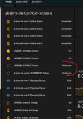
Question
1. Where the old yaml config had Canbus Status for individual BMS - this new one seems to have consolidated it for combined, is that true?
2. as per the screenshot below, Canbus Status for my Sofar sting shows unknown, anyone has a guild on what protocol to use on the JKBMS configuration - and best protocol to choose on the Esp32 Configuration?

Sleeper85
Sunday handyman
- Joined
- Nov 28, 2022
- Messages
- 503
Question
1. Where the old yaml config had Canbus Status for individual BMS - this new one seems to have consolidated it for combined, is that true?
2. as per the screenshot below, Canbus Status for my Sofar sting shows unknown, anyone has a guild on what protocol to use on the JKBMS configuration - and best protocol to choose on the Esp32 Configuration?
View attachment 219528
The canbus status tells you the status of the links between the canbus board and your inverter, if your inverter responds well with the CAN ID 0x305 then this link is considered active. So a status/canbus links, there is no relationship between the number of BMS.
Maybe you still have some leftovers from the old version in HA ?
By default the name is: smartbms CANBUS 1 Status
YAML:
binary_sensor:
  - platform: template
    name: "${name} ${canbus_name} Status"
    id: ${canbus_id}_status
    entity_category: diagnostic
Last edited:
Sleeper85
Sunday handyman
- Joined
- Nov 28, 2022
- Messages
- 503
@chaosnature
I have updated the Esphome. I am using Esphome under Home assistant. I am running last version. See below the log:
INFO ESPHome 2024.5.4
INFO Reading configuration /config/esphome/jk-inverter.yaml...
INFO Updating https://github.com/txubelaxu/esphome-jk-bms.git@main
INFO Detected timezone 'Europe/Bucharest'
INFO Generating C++ source...
INFO Compiling app...
Processing smartbms (board: esp32-s3-devkitc-1; framework: espidf; platform: platformio/espressif32@5.4.0)
--------------------------------------------------------------------------------
HARDWARE: ESP32S3 240MHz, 320KB RAM, 8MB Flash
- framework-espidf @ 3.40407.0 (4.4.7)
- tool-cmake @ 3.16.4
- tool-ninja @ 1.7.1
- toolchain-esp32ulp @ 2.35.0-20220830
- toolchain-riscv32-esp @ 8.4.0+2021r2-patch5
- toolchain-xtensa-esp32s3 @ 8.4.0+2021r2-patch5
Reading CMake configuration...
No dependencies
Compiling .pioenvs/smartbms/src/main.o
Archiving .pioenvs/smartbms/esp-idf/asio/libasio.a
Compiling .pioenvs/smartbms/bootloader_support/src/bootloader_common.o
Compiling .pioenvs/smartbms/bootloader_support/src/bootloader_common_loader.o
Compiling .pioenvs/smartbms/bootloader_support/src/bootloader_clock_init.o
Compiling .pioenvs/smartbms/bootloader_support/src/bootloader_flash.o
Compiling .pioenvs/smartbms/bootloader_support/src/bootloader_mem.o
Compiling .pioenvs/smartbms/bootloader_support/src/bootloader_random.o
Compiling .pioenvs/smartbms/bootloader_support/src/bootloader_random_esp32s3.o
In file included from src/esphome/components/jk_rs485_sniffer/jk_rs485_sniffer.h:6,
from src/esphome/components/jk_rs485_bms/jk_rs485_bms.h:8,
from src/esphome.h:32,
from src/main.cpp:3:
src/esphome/components/jk_rs485_sniffer/binary_output.h:18:7: error: redefinition of 'class esphome:utput::BinaryOutput'
class BinaryOutput {
^~~~~~~~~~~~
In file included from src/esphome/components/binary/light/binary_light_output.h:4,
from src/esphome.h:15,
from src/main.cpp:3:
src/esphome/components/output/binary_output.h:18:7: note: previous definition of 'class esphome:utput::BinaryOutput'
class BinaryOutput {
^~~~~~~~~~~~
Compiling .pioenvs/smartbms/bootloader_support/src/bootloader_utility.o
Compiling .pioenvs/smartbms/bootloader_support/src/esp_image_format.o
Compiling .pioenvs/smartbms/bootloader_support/src/flash_encrypt.o
Compiling .pioenvs/smartbms/bootloader_support/src/secure_boot.o
Compiling .pioenvs/smartbms/bootloader_support/src/flash_partitions.o
Compiling .pioenvs/smartbms/bootloader_support/src/flash_qio_mode.o
Compiling .pioenvs/smartbms/bootloader_support/src/bootloader_flash_config_esp32s3.o
Compiling .pioenvs/smartbms/bootloader_support/src/bootloader_efuse.o
Compiling .pioenvs/smartbms/bootloader_support/src/idf/bootloader_sha.o
Archiving .pioenvs/smartbms/esp-idf/bootloader_support/libbootloader_support.a
Compiling .pioenvs/smartbms/cbor/tinycbor/src/cborencoder_close_container_checked.o
Compiling .pioenvs/smartbms/cbor/tinycbor/src/cborencoder.o
Compiling .pioenvs/smartbms/cbor/tinycbor/src/cborerrorstrings.o
Compiling .pioenvs/smartbms/cbor/tinycbor/src/cborparser_dup_string.o
Compiling .pioenvs/smartbms/cbor/tinycbor/src/cborparser.o
Compiling .pioenvs/smartbms/cbor/tinycbor/src/cborpretty_stdio.o
Compiling .pioenvs/smartbms/cbor/tinycbor/src/cborpretty.o
*** [.pioenvs/smartbms/src/main.o] Error 1
========================= [FAILED] Took 46.05 seconds =========================
Is this the board you are using?
If you have created your own YAML board for ES32-C3 based on Atom S3 and you use GPIO 4 in two places in your configuration you have a conflict.
YAML:
output:
  # ESP LED
  - platform: gpio
    pin: 4
    id: esp_led
    inverted: true
YAML:
  # The sniffer represents the ESP node connected to the JK-BMS PB RS485 bus
  # If address 0x00 is not detected on the RS485 bus, the sniffer will act directly as a master BMS (mode 2, max 15 BMS)
  sniffer1: !include
    file: packages/bms/bms_jk-bms_rs485_pb_sniffer.yaml
    vars:
      sniffer_id: 'sniffer1'
      sniffer_protocol: 'JK02_32S'
      sniffer_uart_id: 'uart_esp_1'
sniffer_talk_pin: 4 # ESP32: 4, ESP32-S3: 8chaosnature
New Member
- Joined
- Sep 15, 2022
- Messages
- 520
I am using Esp32 S3 Lite Board
Something to note is, that with the older Config setup, Canbus status would show connected as normal....so was wondering if the logic has changed, I didn't think I needed to change protocols on the inverter or the BMS settings.
Also - the only reason I am even trying this is for experimental purposes as you know; as opposed to the JK Power BMS - this Version of Inverter BMS (JK-PB2A16S15P) doesn't really need or benefits from this project as the BMS are already detected by the Sofar inverter since JK has already built in the protocols to be detected.
But I am sure if I had success with connecting this project with the inverter/BMS there would be more benefit CAN control-wise over the original factory JK CAN control?
As of now what I am using the technology for (since the CAN refuse to connect) is just for Monitory, bcos though the CAN is failing; the EsP32 board connects and collects and reports the Inverter data as expected......
chaosnature
New Member
- Joined
- Sep 15, 2022
- Messages
- 520
To simplify - As the configuration has now been splitIs this the board you are using?
If you have created your own YAML board for ES32-C3 based on Atom S3 and you use GPIO 4 in two places in your configuration you have a conflict.
YAML:output: # ESP LED - platform: gpio pin: 4 id: esp_led inverted: true
YAML:# The sniffer represents the ESP node connected to the JK-BMS PB RS485 bus # If address 0x00 is not detected on the RS485 bus, the sniffer will act directly as a master BMS (mode 2, max 15 BMS) sniffer1: !include file: packages/bms/bms_jk-bms_rs485_pb_sniffer.yaml vars: sniffer_id: 'sniffer1' sniffer_protocol: 'JK02_32S' sniffer_uart_id: 'uart_esp_1' sniffer_talk_pin: 4 # ESP32: 4, ESP32-S3: 8
Can you list what must be changed and what is Optional to change in the config files when you do the ReadMe guild?
# I have not altered my _sniffer.yaml file
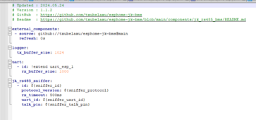
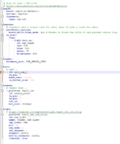
# Edit
are you saying that pin 4 has to change to avoid conflict?
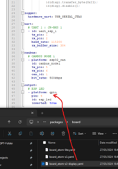
I also did not set or alter any GPIO settings
Last edited:
Sleeper85
Sunday handyman
- Joined
- Nov 28, 2022
- Messages
- 503
Hello, I recently buyed a JK BMS PB2A16S20P, Hardware version V15.XA, running V15.10 firmware and have issues compiling the code for ESP32 - C3 board or for standard ESP32. I have copied packages folder as well as secrets.yaml and i get the following error:
from src/main.cpp:3:
src/esphome/components/jk_rs485_sniffer/binary_output.h:18:7: error: redefinition of 'class esphome:utput::BinaryOutput'
class BinaryOutput {
^~~~~~~~~~~~
In file included from src/esphome/components/binary/light/binary_light_output.h:4,
from src/esphome.h:15,
from src/main.cpp:3:
src/esphome/components/output/binary_output.h:18:7: note: previous definition of 'class esphome:utput::BinaryOutput'
class BinaryOutput {
^~~~~~~~~~~~
Generating LD script .pioenvs/smartbms/memory.ld
Compiling .pioenvs/smartbms/app_trace/app_trace.o
*** [.pioenvs/smartbms/src/main.o] Error 1
========================= [FAILED] Took 607.51 seconds =========================
I have created a new board file for C3 board, and i cannot find what is the issue for not managing to compile.
The content for C3 board is as follows:
# Updated : 2024.05.19
# Version : 1.1
# GitHub : https://github.com/Sleeper85/esphome-jk-bms-can
esp32:
board: esp32-c3-devkitm-1
framework:
type: esp-idf
uart:
# UART 1
- id: uart_esp_1
tx_pin: 21
rx_pin: 20
baud_rate: 115200
rx_buffer_size: 384
canbus:
# CANBUS NODE 1
- platform: esp32_can
id: canbus_node1
tx_pin: 9
rx_pin: 8
can_id: 1
bit_rate: 500kbps
output:
# ESP LED
- platform: gpio
pin: 2
id: esp_led
inverted: true
light:
# ESP Light
- platform: binary
output: esp_led
id: esp_light
name: "${name} On board light"
internal: true
C3 has no onboard led but i will attach one on GPIO2 if it will manage to compile and run successfully.
If i choose board type esp32-s3 the code is compiling successfully but obviously it cannot be flashed to C3 board.
Any ideas?
It is better not to use GPIO 21 and 20 which are assigned to uart0 and logger.
According to the doc GPIO 8 is used for the RGB LED which will be used for the CAN bus status, we could therefore use GPIO 10 for talk pin.
I added a YAML board_esp32-c3-devkitm-1.yaml
GPIOs Summary:
- uart1 tx_pin: 4 (to RS485 board)
- uart1 rx_pin: 5 (to RS485 board)
- uart2 tx_pin: 6 (not used with JK-BMS-PB)
- uart2 rx_pin: 7 (not used with JK-BMS-PB)
- canbus1 tx_pin: 18
- canbus1 rx_pin: 19
- RGB LED: 8
- TALK PIN: 10
Last edited:
Sleeper85
Sunday handyman
- Joined
- Nov 28, 2022
- Messages
- 503
To simplify - As the configuration has now been split
Can you list what must be changed and what is Optional to change in the config files when you do the ReadMe guild?
# I have not altered my _sniffer.yaml file
View attachment 219532View attachment 219533
# Edit
are you saying that pin 4 has to change to avoid conflict?
View attachment 219535
I also did not set or alter any GPIO settings
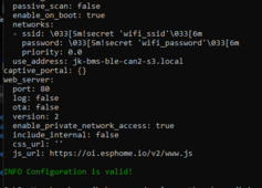
If you want to use an Atom S3 Lite with the new JK-BMS-PB you can follow this guide (draft).
You will need to solder a wire to the CAN bus base for the TALK PIN (gpio 8).
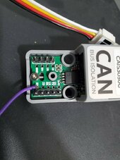
What is the advantage of using this project instead of the CAN communication integrated into the new JK-BMS?
Certainly better charging logic and lots of other customizable options like the inverter_offset_v parameter which is very useful with Deye. We can also add all the AutoCVL, AutoCCL, AutoDCL functions created by @MrPablo . And more to come for sure. I did this at the request of @widget4145
chaosnature
New Member
- Joined
- Sep 15, 2022
- Messages
- 520
Thanks - is it a matter of just downloading the added board_esp32-c3-devkitm-1.yaml into the Board directory and reflashing or do any of the other .yaml files need altering?It is better not to use GPIO 21 and 20 which are assigned to uart0 and logger.
According to the doc GPIO 8 is used for the RGB LED which will be used for the CAN bus status, we could therefore use GPIO 9 for talk pin.
I added a YAML board_esp32-c3-devkitm-1.yaml
GPIOs Summary:
- uart1 tx_pin: 4 (to RS485 board)
- uart1 rx_pin: 5 (to RS485 board)
- uart2 tx_pin: 6 (not used with JK-BMS-PB)
- uart2 rx_pin: 7 (not used with JK-BMS-PB)
- canbus1 tx_pin: 18
- canbus1 rx_pin: 19
- RGB LED: 8
- TALK PIN: 9
chaosnature
New Member
- Joined
- Sep 15, 2022
- Messages
- 520
If you want to use an Atom S3 Lite with the new JK-BMS-PB you can follow this guide (draft).
You will need to solder a wire to the CAN bus base for the TALK PIN (gpio 8).
View attachment 219536
What is the advantage of using this project instead of the CAN communication integrated into the new JK-BMS?
Certainly better charging logic and lots of other customizable options like the inverter_offset_v parameter which is very useful with Deye. We can also add all the AutoCVL, AutoCCL, AutoDCL functions created by @MrPablo . And more to come for sure. I did this at the request of @widget4145
Thanks..
I knew there were many benefits thanks for confirming.
"If you want to use an Atom S3 Lite with the new JK-BMS-PB you can follow this guide (draft)."
What about for BLE - does it work out of the box ?
Sleeper85
Sunday handyman
- Joined
- Nov 28, 2022
- Messages
- 503
Thanks - is it a matter of just downloading the added board_esp32-c3-devkitm-1.yaml into the Board directory and reflashing or do any of the other .yaml files need altering?
Yes, but this concerns @virus100b request.
Sleeper85
Sunday handyman
- Joined
- Nov 28, 2022
- Messages
- 503
Thanks..
I knew there were many benefits thanks for confirming.
"If you want to use an Atom S3 Lite with the new JK-BMS-PB you can follow this guide (draft)."
What about for BLE - does it work out of the box ?
I haven't tried it but it may work via Bluetooth.
You should use this sample YAML to test it.
chaosnature
New Member
- Joined
- Sep 15, 2022
- Messages
- 520
Sleeper85
Sunday handyman
- Joined
- Nov 28, 2022
- Messages
- 503
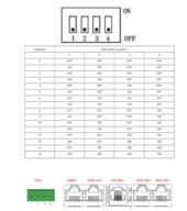
According to the below - the address 0 will be master (when all Dip Switches are set to off?)
and the Address 1 would be the first slave (1000) ? how do you guys translate this to 0x000 format,
newbie question...
View attachment 219541
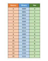
But if you want to take the BMS information from BLE then you should not modify the current config of your dip switches.
Just bought Atomic RS485 base for AtomS3 and have connected CAN unit to AtomS3 port. What will be the correct config for this Atomic RS485?
Wondering about talk pin configuration. If I look at Atomic RS485 base schematics DI is connected to ground and on your documentation it is connected to TX etc. Can you please help with this? Will this be possible to use Atomic RS485?
Wondering about talk pin configuration. If I look at Atomic RS485 base schematics DI is connected to ground and on your documentation it is connected to TX etc. Can you please help with this? Will this be possible to use Atomic RS485?
Similar threads
- Replies
- 27
- Views
- 695
- Replies
- 8
- Views
- 833
- Replies
- 19
- Views
- 1K
- Replies
- 4
- Views
- 719


