diy solar

diy solar

JK-BMS-CAN with new Cut-Off Charging Logic (open-source)

Found My Issue:
I had the CAN polarity wrong (so just switch them over)
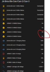
1717514068910.png
======================================================

My Test result with Sofar Inverter (sofar_hyd3k-6k breed) on JK-PB2A16S15P x 2

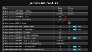
First of all, Pylon Protocol will not work when selected on the JKBMS (info to help others)
The protocols i tested working are the once tick good
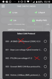
1717511332507.png1717511367516.png

Secondly - (not sure if this applies to me only) The CAN Cable must be plugged in to have the Esp32 CAN connect (BLE Mode)
Every time I remove the Wire CAN between the inverter and the JKBMS the Esp stop blinking
Yes - If your esp32 s3 lite is not blinking it means no CAN connection (good job for those who worked on the Lighting aspect of the program).


Since I have chosen GoodWe Protocol from the JKBMS - i decided to set a similar setting on the ESP side thinking this was why it disconnects without the original JKBMS CAN Wire to CAN port. Restarted but the same result

1717511904626.png
For me, I am very o.k with that setup.
 
Last edited:
So Basically UAT test for sofar_hyd3k-6k on JK-PB2A16S15P (Inverter BMS) is a Pass

I will be testing Solis on JK-B2A24S15P (Power BMS) next....
 
Found My Issue:
I had the CAN polarity wrong (so just switch them over)
View attachment 219607
======================================================

My Test result with Sofar Inverter (sofar_hyd3k-6k breed) on JK-PB2A16S15P x 2

First of all, Pylon Protocol will not work when selected on the JKBMS (info to help others)
The protocols i tested working are the once tick good
View attachment 219575View attachment 219576

Secondly - (not sure if this applies to me only) The CAN Cable must be plugged in to have the Esp32 CAN connect (BLE Mode)
Every time I remove the Wire CAN between the inverter and the JKBMS the Esp stop blinking
Yes - If your esp32 s3 lite is not blinking it means no CAN connection (good job for those who worked on the Lighting aspect of the program).


Since I have chosen GoodWe Protocol from the JKBMS - i decided to set a similar setting on the ESP side thinking this was why it disconnects without the original JKBMS CAN Wire to CAN port. Restarted but the same result

View attachment 219581
For me, I am very o.k with that setup.

The goal of using this project with the new JK-BMS-PB is to no longer use the CAN links between the JK-BMS-PB master and the inverter (therefore the JK-BMS logic) but only between the ESP32 and inverter.

Concerning the CAN protocol :
  • BMS name is the name of the BMS that will be sent on the can bus (just a name) in your case you are telling it that you are a GoodWe battery.
  • BMS Protocol is the protocol that will be used, this corresponds to the CAN IDs that will be sent. See this table. GENERAL only contains base IDs and should not be used.

I don't know why you are still using 4x ESP32 because the goal is to do multi-BMS (the BMS information is combined).
So in Bluethooth you should be able to supervise two BMS (max 3) via a single ESP32 and therefore a single canbus link to your inverter.

By using a UART expansion card (as is done with the PVbrain2 board) you could connect your 4 BMS to the same ESP32-S3 then share the information to two different CAN bus (one link per inverter).
 
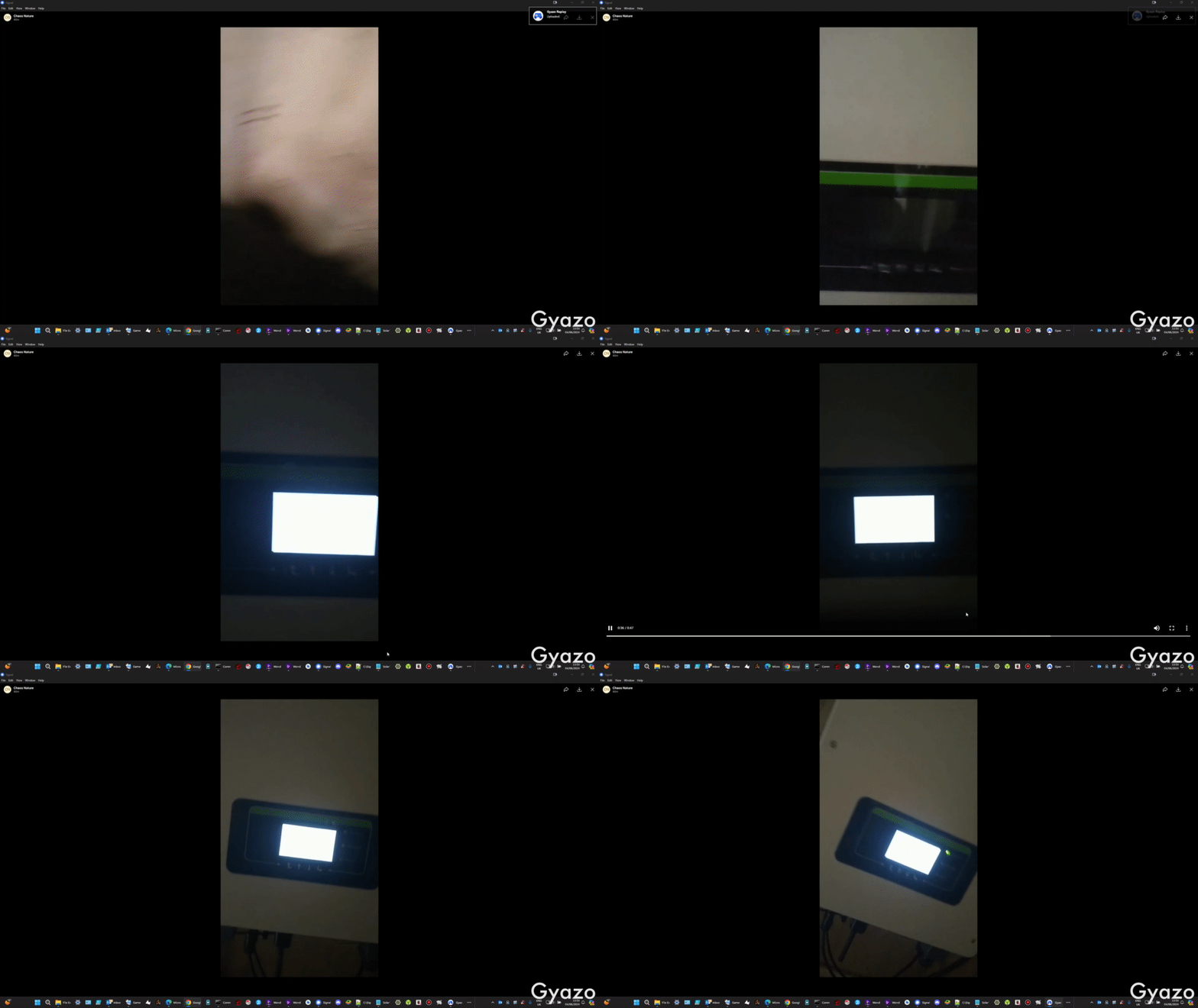
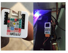
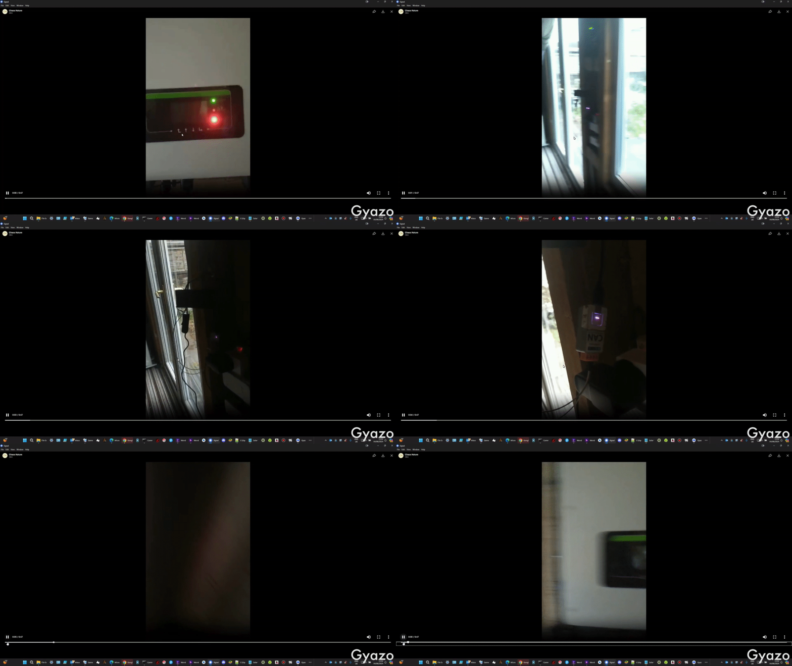
As shown in the video by @chaosnature I worked a little on the operation of the RGB LED of ESP32-S3 and Atom S3. I did this very quickly and it will be possible to do many more things but for the moment it flashes purple when the can bus link is OK.
 
Just bought Atomic RS485 base for AtomS3 and have connected CAN unit to AtomS3 port. What will be the correct config for this Atomic RS485?
Wondering about talk pin configuration. If I look at Atomic RS485 base schematics DI is connected to ground and on your documentation it is connected to TX etc. Can you please help with this? Will this be possible to use Atomic RS485?

Currently RS485 is only used for connection to the new JK-BMS-PB.

Support for the new JK-BMS via UART-RS485 is achieved thanks to the @txubelaxu component.

In his example and his code he uses an RS485 board with a TALK PIN (which is not the case with good bidirectional boards).
So I don't know how this code will react with another board without TALK PIN.

What exactly do you want to do?
 
According to the below - the address 0 will be master (when all Dip Switches are set to off?)

and the Address 1 would be the first slave (1000) ? how do you guys translate this to 0x000 format,
newbie question...

View attachment 219541

# Edit - off the back of this statement.....

View attachment 219543

If you are monitoring the new JK-BMS-PB via Bluetooth then you should not use the example YAML for monitoring via RS485.
 
The goal of using this project with the new JK-BMS-PB is to no longer use the CAN links between the JK-BMS-PB master and the inverter (therefore the JK-BMS logic) but only between the ESP32 and inverter.

Concerning the CAN protocol :
  • BMS name is the name of the BMS that will be sent on the can bus (just a name) in your case you are telling it that you are a GoodWe battery.
  • BMS Protocol is the protocol that will be used, this corresponds to the CAN IDs that will be sent. See this table. GENERAL only contains base IDs and should not be used.

I don't know why you are still using 4x ESP32 because the goal is to do multi-BMS (the BMS information is combined).
So in Bluethooth you should be able to supervise two BMS (max 3) via a single ESP32 and therefore a single canbus link to your inverter.

By using a UART expansion card (as is done with the PVbrain2 board) you could connect your 4 BMS to the same ESP32-S3 then share the information to two different CAN bus (one link per inverter).
I don't know why you are still using 4x ESP32 because the goal is to do multi-BMS (the BMS information is combined).

I dont have 4 x ESP - i did and yes i know the goal is to combine, so on my second string (Sofar) i have combined the ESP; i am now only using 1

The First String (solis ) is still on the old , so have not been combined yet , that is next.

As for have both string on one ESP , i cannot do that as the second string is too far from the first string and will not get a stable connection
 
If you are monitoring the new JK-BMS-PB via Bluetooth then you should not use the example YAML for monitoring via RS485.
The monitoring is via wireless.

I am off the monitoring mode now as i got it working - as per the above screenshots.
 
Currently RS485 is only used for connection to the new JK-BMS-PB.

Support for the new JK-BMS via UART-RS485 is achieved thanks to the @txubelaxu component.

In his example and his code he uses an RS485 board with a TALK PIN (which is not the case with good bidirectional boards).
So I don't know how this code will react with another board without TALK PIN.

What exactly do you want to do?

I managed to connect my two DIY batteries witch JK PB BMSes using AtomS3 BLE connections to the BMSes and CAN to inverter - this is working good and I love it :)
But I'd like to change BLE connections with one RS485 connection to JK PB BMSes.
Thank you for @txubelaxu component link, now I see that I'll need the "talk pin" solution and mentioned there TTL to RS485 converter - this will let the Atom to act as a master BMS.
 
Last edited:
Found My Issue:
I had the CAN polarity wrong (so just switch them over)
View attachment 219607
======================================================

My Test result with Sofar Inverter (sofar_hyd3k-6k breed) on JK-PB2A16S15P x 2

First of all, Pylon Protocol will not work when selected on the JKBMS (info to help others)
The protocols i tested working are the once tick good
View attachment 219575View attachment 219576

Secondly - (not sure if this applies to me only) The CAN Cable must be plugged in to have the Esp32 CAN connect (BLE Mode)
Every time I remove the Wire CAN between the inverter and the JKBMS the Esp stop blinking
Yes - If your esp32 s3 lite is not blinking it means no CAN connection (good job for those who worked on the Lighting aspect of the program).


Since I have chosen GoodWe Protocol from the JKBMS - i decided to set a similar setting on the ESP side thinking this was why it disconnects without the original JKBMS CAN Wire to CAN port. Restarted but the same result

View attachment 219581
For me, I am very o.k with that setup.
i understand why you got confused now.....

In the screenshot where I circled the Canbus , they are both pointing to the same Entity......that is becos i was using the same card and just overwriting the entities when i was updating my cards.
 
I managed to connect my two DIY batteries witch JK PB BMSes using AtomS3 BLE connections to the BMSes and CAN to inverter - this is working good and I love it :)
But I'd like to change BLE connections with one RS485 connection to JK PB BMSes.
I know - its so nice the outcome , lol

i can't wait to see how it will look when i use this chip with the screen
1717526294842.png
 
@Sleeper85

The goal of using this project with the new JK-BMS-PB is to no longer use the CAN links between the JK-BMS-PB master and the inverter (therefore the JK-BMS logic) but only between the ESP32 and inverter.

Well, the only way I could get my setup to work is by bridging the link between the ESP and the inverter and then taking the CAN-H and CAN-L back into the Master Battery BMS
1717527483206.png

The ESP device is blinking so I know it's using your logic and not the JKBMS CAN logic.

if anyone has a sofar they can confirm this as well.
I definitely tested the JKBMS protocols and saw the inverter go offline when I chose one that was not compatible as per my previous screenshots
 
@Sleeper85


Well, the only way I could get my setup to work is by bridging the link between the ESP and the inverter and then taking the CAN-H and CAN-L back into the Master Battery BMS
View attachment 219682

The ESP device is blinking so I know it's using your logic and not the JKBMS CAN logic.

if anyone has a sofar they can confirm this as well.
I definitely tested the JKBMS protocols and saw the inverter go offline when I chose one that was not compatible as per my previous screenshots

Your config is not good. You must not connect the canh, canl coming from your BMS Master. Only canh and canl coming from esp32 must be connected.

With your current config you have two Masters sending different instructions... It's anarchy 😅

Sofar should work with bms name 'PYLON' and protocol 'PYLON +'.
O.k - i gat to figure out why the battery throws error when i remove the bridge CAN-h/l cable to the batt
 
Your config is not good. You must not connect the canh, canl coming from your BMS Master. Only canh and canl coming from esp32 must be connected.

With your current config you have two Masters sending different instructions... It's anarchy 😅

Sofar should work with bms name 'PYLON' and protocol 'PYLON +'.
And yes it is Anarchy , the behaviour right now,

It's stable when i turn off or disconnect the ESP CAN,

i did everything correctly - not sure what is missing

i am going back to set the protocols both on the inverter and the BMS to Pylontech again - will report here
 
Nope - same result

Each time i remove the bridge plug failure error on the Inverter
when i plug it back in Esp starts to flash


i wasn't ready to flash the Solis setup...but this is now prompting me to test it on the solis
i will use exactly the same code , only change the names

BRB...
 
O.k

Just Flashed the Solis

It say CAN o.k on the inverter - But Battery name fail
1717537644314.png

It is also not displaying the SOC on the inverter . it just says 0%

Also the Atom S3 Lite Display does not come on (a little disappointed :) )

so i think there is a problem somewhere...

# Edit

Changed the name and protocol to SMA and rebooted the Inverter and it has the green light now, with no errors

But Why no light on the ESP display.....please check if the lighting pin on my model is different from the default set for the normal ESP chip

# Edit

Oh, i forgot the reason why i flashed the Solis this night - So this means the config is fine, therefore what is wrong with the same config not working on the Sofar ?

1717539746138.png1717539815653.png
It would be nice to have the Sofar guys test again with the new release....
 
Last edited:
@chaosnature

Concerning Atom S3 display there is no RGB LED but only a display. The goal is therefore to display the status of the can bus and other components on the display. I don't have an Atom S3 display, @Der_Hannes has done a lot of work with logos to display nice things on this display but he hasn't given me the code yet. Don't forget to import the yaml board for Atom S3 display instead of Lite, there is already some code for the display. You must adapt the main YAML to your configuration (comment/uncomment the correct board).

Concerning Sofar and the CAN bus links, there has not really been a change in the CAN bus protocol code and therefore it should work with the same parameters as before. What is the model of your Sofar? With which protocol does your Sofar work when connected to the JK-BMS-PB Master?

For Solis based on @MrPablo testing, SMA is the best protocol to use.(y)

Concerning the charging parameters, have you configured the values for Li-ion at the end of the smartbms section?
 
This is the board i uncommented
1717568638800.png

As for Lion: I just noticed and corrected it now - Hopefully, this was why it is not discharging.
1717569561111.png

For My chip - this is incorrect?

As for the Sofar
The model is: HYD 3600-ES

It uses Protocol
Pylontech (Not got this to work yet - it did with the old code but still when bridged)
GoodWe and
Deye


Solis:
Just found out this morning that it charges but would not discharge - i have seen this before and i bliv i can trouble shoot this one

thanks for you support...


# Edit

Amended and now flashing this: - Thanks to @Der_Hannes
1717569125385.png
 
Last edited:
@chaosnature

Concerning Atom S3 display there is no RGB LED but only a display. The goal is therefore to display the status of the can bus and other components on the display. I don't have an Atom S3 display, @Der_Hannes has done a lot of work with logos to display nice things on this display but he hasn't given me the code yet. Don't forget to import the yaml board for Atom S3 display instead of Lite, there is already some code for the display. You must adapt the main YAML to your configuration (comment/uncomment the correct board).
FYI AtomS3 display is working just fine displaying SOC, Voltage, Current, CAN status ,ESP status and current charging state.

IMG_4725.jpg
 
Error While flashing: the board_atom-s3-display.yaml

Edit
Clean the build and its flashing now..
 
Last edited:
As for the Discharge issue - i had to turn off Automatic Discharge for my Solis inverter to be able to discharge.
 
Did you make any changes to the board_atom-s3-display.yaml file?

I think i am missing something - what needs to be declared?

View attachment 219831
Help -
No changes to the file. Just make sure to uncomment all 5 lines:

YAML:
device_board: !include
    file: packages/board/board_atom-s3-display.yaml
    vars:
      smartbms_id: 'smartbms1'
      canbus_id: 'canbus1'
 
Last edited:

diy solar

diy solar
Back
Top