diy solar

diy solar

JK-BMS-CAN with new Cut-Off Charging Logic (open-source)

No changes to the file. Just make sure to uncomment all 5 lines:
Hi,
nope, no changes.
Just make sure that you uncommented all 5 lines:
YAML:
device_board: !include
    file: packages/board/board_atom-s3-display.yaml
    vars:
      smartbms_id: 'smartbms1'
      canbus_id: 'canbus1'
Thanks...that did it....Zero Knowledge when it comes to coding :)
 
So that's all the UAT test done for :
SOL-3K-RHI-48ES on x2 JK-B2A24S15P (Power BMS)

Pass (Except for someone needs to Confirm if it is Normal to have to turn off Automatic Discharge to have the Inverter Discharging)

Thanks to all those involved.....
 
Last edited:
It is better not to use GPIO 21 and 20 which are assigned to uart0 and logger.

According to the doc GPIO 8 is used for the RGB LED which will be used for the CAN bus status, we could therefore use GPIO 10 for talk pin.

I added a YAML board_esp32-c3-devkitm-1.yaml

GPIOs Summary:
  • uart1 tx_pin: 4 (to RS485 board)
  • uart1 rx_pin: 5 (to RS485 board)
  • uart2 tx_pin: 6 (not used with JK-BMS-PB)
  • uart2 rx_pin: 7 (not used with JK-BMS-PB)
  • canbus1 tx_pin: 18
  • canbus1 rx_pin: 19
  • RGB LED: 8
  • TALK PIN: 10
You are right. I just missed to look on the documentation to see for which uart are used 21 and 20. At the end i manage to compile the code before i see that you created a C3 yaml. I have created one by modifying the board made for esp32-s3-devkitc-1
Looks like the code for C3 don't like this part:

light:
# ESP Light
- platform: binary
output: esp_led
id: esp_light
name: "${name} On board light"
internal: true

But compiled with this:

light:
# https://esphome.io/components/light/esp32_rmt_led_strip
- platform: esp32_rmt_led_strip
id: esp_light
name: ${name} ESP Light
rgb_order: GRB
pin: 2
num_leds: 1
rmt_channel: 0
chipset: ws2812
entity_category: config
internal: true


The full file content that i manage to compile is:

# Updated : 2024.05.18
# Version : 1.1
# GitHub : https://github.com/Sleeper85/esphome-jk-bms-can

esp32:
board: esp32-c3-devkitm-1
framework:
type: esp-idf

esphome:
# Standard uses a single line for data, Dual IO uses 2 lines for data.
platformio_options:
board_build.flash_mode: dio # Needed to flash the ESP32-S3 and prevent reboot loop
on_boot:
then:
- light.turn_on:
id: esp_light
red: 50%
blue: 50%
green: 0%
brightness: 50%

uart:
# UART 0 : uart used for ESP32 flashing and logs, can be released if necessary (tx_pin: 43, rx_pin: 44)
# UART 1
- id: uart_esp_1
tx_pin: 20 # Modbus board DI pin to ESP TX pin
rx_pin: 21 # Modbus board RO pin to ESP RX pin
baud_rate: 115200
rx_buffer_size: 384

canbus:
# CANBUS NODE 1
- platform: esp32_can
id: canbus_node1
tx_pin: 9
rx_pin: 8
can_id: 1
bit_rate: 500kbps

light:
# https://esphome.io/components/light/esp32_rmt_led_strip
- platform: esp32_rmt_led_strip
id: esp_light
name: ${name} ESP Light
rgb_order: GRB
pin: 2
num_leds: 1
rmt_channel: 0
chipset: ws2812
entity_category: config
internal: true

For now i cannot change the rx and tx pins for uart as i am away from home for a few weeks. I have left the PB type BMS connected to C3 board but i don't have can module attached to the inverter since i did not have enough time for testing (as you know i had issues flashing and struggle for 2 days to find the solution). For the moment Inverter is using the old JK BMS connected to ESP32 running v1.17.5 perfectly fine. When i will return home i will attach TJA can board to C3 and hopefully have a good communication with the inverter.

I will have a second pack of cells and another PB BMS. With this setup i need to set first BMS as slave (address 01) and second (02) and esp will combine them and sent the data to the inverter. Right?
 
O.k - i gat to figure out why the battery throws error when i remove the bridge CAN-h/l cable to the batt
I think your setup is missing the terminal resistor. Maybe Atom CAN has no termination resistor and the battery has one. A can network you need 2 termination resistors of 120ohms at each end of network.

Turn off invertor and measure the resistance between Can H & L with battery disconnected and ESP connected to the inverter. If you read 120Ohm you are missing a terminal resistor and you need to add a 120ohms resistor between can h and can. A correct configured can network need to measure 60ohm between Can H & L.
 
@virus100b

Normally there is an RGB LED on your board connected to GPIO 8. Try using the yaml that I created for ESP32-C3 and if I need to make corrections tell me.

When the LED flashes purple, the CAN bus status is OK.
 
I think your setup is missing the terminal resistor. Maybe Atom CAN has no termination resistor and the battery has one. A can network you need 2 termination resistors of 120ohms at each end of network.

Turn off invertor and measure the resistance between Can H & L with battery disconnected and ESP connected to the inverter. If you read 120Ohm you are missing a terminal resistor and you need to add a 120ohms resistor between can h and can. A correct configured can network need to measure 60ohm between Can H & L.
I did what you suggested it read 119/120Ohms was fluctuating to other values but mainly 120...
 
@Sleeper85 Just received my RS485 board with "talk pin", connected it with my 2 JK PB BMSes and it is extremaly unstable, slow and practically unusable.
I thought that this will be better solution than BLE connections but from what I see is that your BLE solution works as expected and it is very stable.

How are the update_interval values of the bms and smart bms set?
Which ESP32 board do you use?
 
@cinusik

How many BMS and how did you configure the BMS dip switches?

2 BMSes, tried both variants - mode 1 and mode 2, dip switches set according to variant used - both unstable. If you have confirmation that this is working for 7 bms'es on AtomS3 Lite, than maybe display code is causing too much load to the ESP causing it to lag and be unstable? Just my thoughts. Will do more testing when I'll have time and let you know. Will try to not use display code and we will see if it will help.

EDIT: And one more question @Sleeper85 . Does @widget4145 using all the entities pushed to HA or he commented lot of them? Maybe too much entities updates pushed to HA is causing lags and unstability?
 
Last edited:
I have never seen my system functioning like this before - its so stable

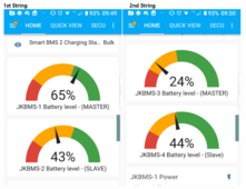
the only issue which i can live with is the fact that the SoC keep leaving each other.
They marry when it gets to the top-end (%100) but then divorce after (40 to 10%) halfway through.


1717752129363.png

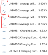
I am not too worried about it bcos I have been monitoring the average voltage and they stay close together - which lets me know the batteries are balancing and syncing, and that one is not overworking

1717751940510.png

The last time I raised this dysfunction - I was told its to do with columnbs counting -tried to read up on columnbs counting was just taking me too deep into electronics jargons, so I just left it alone.

I think even JK themselves haven't yet figured out a solution to this yet.....
 
2 BMSes, tried both variants - mode 1 and mode 2, dip switches set according to variant used - both unstable. If you have confirmation that this is working for 7 bms'es on AtomS3 Lite, than maybe display code is causing too much load to the ESP causing it to lag and be unstable? Just my thoughts. Will do more testing when I'll have time and let you know. Will try to not use display code and we will see if it will help.

EDIT: And one more question @Sleeper85 . Does @widget4145 using all the entities pushed to HA or he commented lot of them? Maybe too much entities updates pushed to HA is causing lags and unstability?

@widget4145 uses all entities. Good idea to do the test without the code for the display.
But you say it works well in Bluetooth with or without the display?
 
I have never seen my system functioning like this before - its so stable

the only issue which i can live with is the fact that the SoC keep leaving each other.
They marry when it gets to the top-end (%100) but then divorce after (40 to 10%) halfway through.


View attachment 220337

I am not too worried about it bcos I have been monitoring the average voltage and they stay close together - which lets me know the batteries are balancing and syncing, and that one is not overworking

View attachment 220336

The last time I raised this dysfunction - I was told its to do with columnbs counting -tried to read up on columnbs counting was just taking me too deep into electronics jargons, so I just left it alone.

I think even JK themselves haven't yet figured out a solution to this yet.....

Maybe your BMS are not all calibrated the same. Voltage and Current can be calibrated.
 
@widget4145 uses all entities. Good idea to do the test without the code for the display.
But you say it works well in Bluetooth with or without the display?
Yes, bluetooth working great with the display.

EDIT: Which mode @widget4145 is using? BMS as a master 0x00 and ESP as a sniffer or BMSes start with 0x01 and ESP as a sniffer?
 
Last edited:
Maybe your BMS are not all calibrated the same. Voltage and Current can be calibrated.
I have made sure the BMS pair has the same voltage and Current values set

# Different Topic
This is why it's so cool to have HA manage your setup.

- Problem
I had Automation to automatically charge my Solis (1st string) (as no such integration exists yet for Sofar 2nd String) - every time it came on and started changing the 1st string as expected, the second string started to discharge as well obviously because there is a requested current from 1st string

- Solution
So I came up with an idea to turn off the "Discharge Entities" of the 2nd string each time the state of the Octopus entity turns to "On" and vise vasa.

- Result
Just waiting to see if it works...
:)
 
Maybe your BMS are not all calibrated the same. Voltage and Current can be calibrated.
Just a little guidance on the calibration aspect

What do I enter into the current Calibration - I mean I have current for both BMS's, do I just choose one value and make sure it's entered the same for both?

1717766126122.png

1717766236252.png
 

diy solar

diy solar
Back
Top