diy solar

diy solar

JK-BMS-CAN with new Cut-Off Charging Logic (open-source)

Hi , I am trying to connect my jk bms to Growatt inverter (SPF5000ES ) , I am using SN65HVD230 3.3V can board and ESP 32 dev board , But seems it is not communicate with inverter.

settings with PYLON/PYLON 1.2 and inverter side set battery type as Li and protocol 52.

using ESP32_LFP_BLE_jk-bms-can.yaml .

in log file i can see some data sending msgs , but no acks

[07:43:22][W][component:237]: Component esp32_ble took a long time for an operation (73 ms).
[07:43:22][W][component:238]: Components should block for at most 30 ms.
[07:43:24][main:1487]: send can id: 0x35C hex: c0 0
[07:43:25][W][component:237]: Component interval took a long time for an operation (1005 ms).
[07:43:25][W][component:238]: Components should block for at most 30 ms.
[07:43:25][jk_bms_ble:327]: Cell info frame (version 2, 300 bytes) received
[07:43:25][W][component:237]: Component esp32_ble took a long time for an operation (62 ms).
[07:43:25][W][component:238]: Components should block for at most 30 ms.
[07:43:26][main:1757]: send can id: 0x35E ASCII : PYLON
[07:43:27][W][component:237]: Component interval took a long time for an operation (1006 ms).
[07:43:27][W][component:238]: Components should block for at most 30 ms.
[07:43:27][main:1122]: send can id: 0x359 hex: 0 0 0 0 2 0 0 0
[07:43:28][W][component:237]: Component interval took a long time for an operation (1005 ms).
[07:43:28][W][component:238]: Components should block for at most 30 ms.
[07:43:28][main:1357]: Alarm Status : NoAlarm
[07:43:28][main:1403]: send can id: 0x351 hex: 28 2 e8 3 b0 4 d8 1
[07:43:28][main:1404]: Charge Status : Bulk
[07:43:29][W][component:237]: Component interval took a long time for an operation (1015 ms).
[07:43:29][W][component:238]: Components should block for at most 30 ms.
[07:43:29][jk_bms_ble:327]: Cell info frame (version 2, 300 bytes) received
[07:43:29][main:1440]: send can id: 0x355 hex: 34 0 62 0 50 14 ff 2
[07:43:30][W][component:237]: Component interval took a long time for an operation (1007 ms).
[07:43:30][W][component:238]: Components should block for at most 30 ms.
[07:43:30][main:1465]: send can id: 0x356 hex: 81 14 b 0 24 1 88 0
[07:43:31][W][component:237]: Component interval took a long time for an operation (1006 ms).
[07:43:31][W][component:238]: Components should block for at most 30 ms.
[07:43:31][main:1487]: send can id: 0x35C hex: c0 0
[07:43:32][W][component:237]: Component interval took a long time for an operation (1005 ms).
[07:43:32][W][component:238]: Components should block for at most 30 ms.
[07:43:32][jk_bms_ble:327]: Cell info frame (ver

blue LED is not blinking and interface display CAN bus status as OFF .
if anyone connected with Growatt , colud you please share your exact setup ?
 
I did what you suggested it read 119/120Ohms was fluctuating to other values but mainly 120...
That means that you have just one termination resistor on your can bus, you need to read 60 Ohm. Just add a 120 ohm resistor near your CAN connection to ESP and should work. Did you try to measure the can network resistance with battery connected ?(Inverter and buttery must be off)
 
That means that you have just one termination resistor on your can bus, you need to read 60 Ohm. Just add a 120 ohm resistor near your CAN connection to ESP and should work. Did you try to measure the can network resistance with battery connected ?(Inverter and buttery must be off)
Genius

I didn't have a 120 ohms resistor but had a few 60 ohms and put them in parallel - as soon as I bridged it and remove the ethernet to the battery it shows green.

1717861874461.png

I now just wonder why I don't have the same issue on the Solis string
...its a different BMS though, those are Poser BMS maybe they already have the terminal resistance built in?

thanks...
 
at rest i have a delta v on each of the strings

Sting 1 = 0.030 v
String 2 = 0.003 v as per the below screenshot

1717863095818.png

is this what we use the Voltage Offset (which I can no longer locate in the settings - or has it been renamed) ?
 
@Sleeper85 @virus100b

One other-thing - The Inverter BMS beeps every second since i have now removed the cable, is this normal behaviour to beep constantly, will the BMS not wear out its speaker after some time like that :)

the Power BMS doesn't beep like that except when it's making that initial connection to the Esp Chip...

Please advise...
 
Genius

I didn't have a 120 ohms resistor but had a few 60 ohms and put them in parallel - as soon as I bridged it and remove the ethernet to the battery it shows green.

View attachment 220659

I now just wonder why I don't have the same issue on the Solis string
...its a different BMS though, those are Poser BMS maybe they already have the terminal resistance built in?

thanks...

You have to put them in series to have 120 Ohms. So it works with 60 Ohms.

Is it with the Atomic CAN bus base?
 
When I did electronics engineering, they taught us how to calculate the resistor resistance just from the colour coding on it...but I have completely forgotten how to.

Anyway, I thought I had already measured and labelled by resistor packs but turns out that set was labelled wrong...what you see in the above screenshot was 566 or so ohms each, when I paralleled them it came to 230 ohms or so...
so when I series them and it stopped working I had to measure with my meter again.

now I have to place 165 ohms and it's all good now.

even the 25xohms stopped working which was magic to my eyes as they did work before even after the inverter reboot.

# Edit

I think I get it now
I remember during my research on the order project that 3.3 volts don't need the resistor and 5 v does, so the resistor is to reduce the voltage to below 5v.

And the Solis Inverter CAN can take 3.3 and 5v (So I have answered my own question).
 
Last edited:
Genius

I didn't have a 120 ohms resistor but had a few 60 ohms and put them in parallel - as soon as I bridged it and remove the ethernet to the battery it shows green.

View attachment 220659

I now just wonder why I don't have the same issue on the Solis string
...its a different BMS though, those are Poser BMS maybe they already have the terminal resistance built in?

thanks...
Is not good to put 2 x 60Ohm in paralel. You need to put 2 In series to obtain one resitor of 120ohm.
2 of 60 in series make 120Ohm
2 in paralel will make 30ohm.

That why on a can bus you need to have 2 resistors on giving 60ohm total. With what you have now you have 120 ohm from invertor and 30ohm from your two resistors in paralel. This will give you 24ohm, way to less. Here is a calculator to see.
 
Was'nt gonna raise this concern until I knew my setup was 100% which it now is.

Turning off the Discharge Switch disables charging - I am sure this was not how it was intended guys, if not what's the purpose?

If you turn off discharge - it is supposed to stop discharging whilste still charging.....can someone else check and confirm this is not just happening to my setup.?##

and I find that automating the toggling on/off of this switch trips off my 40 A breaker switch between the batteries....??
On my BMS is not working at all but i don't use the BMS right now is just connected to esphome. Charge, discharge and balance are disabled from BMS, If i turn the switch on from esphome is turning back off in 2 seconds and in BMS i cannot see the movement. If i change charge or discharge switch from BMS i can see the change in Esphome so is some kind of unidirectional command.
 
i have made a new discovery with my attempt to have 2 parallel batteries connected to work together with just one master - i have been talking with JK and they have refused to either show me how to or send me a firmware to update and bring the old up-to-date with the new.

i feel this is not very professional to be selling products of the same model and have different features - how would customers know what they are getting....i might be very wrong and this might be a no-wrong from JK.
But below you will see the pain it is causing me on this project...this is what i sent to them after they asked me to send a screenshot of the firmware versions between them - both modules are jk2a24s15p


View attachment 200221
View attachment 200226

View attachment 200227

Hi JK,


View attachment 200222

New Firmware
View attachment 200223


Same settings same battery same current same capacity same voltage - BUT DIFFERENT SOC VALUES
View attachment 200224
View attachment 200225

I thought it might be helpful to know thats why i am posting this here , might not be relevant - i dont know...
This sounds familiar… I have a bug between my JK and Solis where it just stops charging for no good reason, and seems to settle on a full voltage of around 54/55v, but full for me is 58.8V. The solution is to log into the JK via Bluetooth on my phone and change the battery capacity; every few days I have to change it to either 400ah or 100ah and it will instantly start charging again and behave itself for a few days until I have to do it again. I assumed it was the code from the project I was using at fault (not this project’s code), but maybe it’s actually the firmware on the JK BMS? I’ve just yesterday flashed my ESP32 with the code from this project so will now seem if it still does the same thing.
 
There is an issue with the soft 100% and the RCV 100% trigger with the new JK PB BMS. With my SMA once the soft 100% is reached the SMA carries on charging and waits until the RCV cell voltage is triggered on one cell, only at that point does the SMA curtail charging. This is closed loop using the SMA Canbus protocol but it also works with SMA using Pylontech, Deye and Goodwe Canbus. Other inverters are taking the soft 100% as the point to stop charging but based on my SMA setup the JK is still allowing a charge. This points to it being more likely its these inverters that have the issue but it could still be the JK.
 
It was not happening ... i am gonna keep an eye on it and see if it goes wrong again.......and report back here
I had that problem in my Solis too - it would just keep discharging beyond its set stop point, and I would find the battery had over discharged and the JK had to take over with an under voltage protection and shut the pack down. My best guess was that even without a load, the Solis still takes about 65W for itself, so overnight in the winter it’s taken the best part of 1kwh(!) after it was told to stop…?
 
@Sleeper85 @virus100b

One other-thing - The Inverter BMS beeps every second since i have now removed the cable, is this normal behaviour to beep constantly, will the BMS not wear out its speaker after some time like that :)

the Power BMS doesn't beep like that except when it's making that initial connection to the Esp Chip...

Please advise...

I don't have a JK-BMS-PB. Maybe you need to configure the BMS dip switches to have two slaves without a master?
So BMS1 with address 1 and BMS2 with address 2? Address 0 is that of the Master.


I imagine that only the Master can communicate on the CAN bus which is no longer necessary. Maybe it's a beep that indicates a CAN bus link problem.
Thanks - this is old,
the issue was bfor i added the resistors...
 
This sounds familiar… I have a bug between my JK and Solis where it just stops charging for no good reason, and seems to settle on a full voltage of around 54/55v, but full for me is 58.8V. The solution is to log into the JK via Bluetooth on my phone and change the battery capacity; every few days I have to change it to either 400ah or 100ah and it will instantly start charging again and behave itself for a few days until I have to do it again. I assumed it was the code from the project I was using at fault (not this project’s code), but maybe it’s actually the firmware on the JK BMS? I’ve just yesterday flashed my ESP32 with the code from this project so will now seem if it still does the same thing.
The new multi-code seem to be more stable - especially if you have multi-battery config.

Also Sleeper85 advised me to check that the Voltage and Amp are the same on both BMS and calibrate the Current and Voltage on the Esp side which i did

it's since been behaving itself.

I find the pb jk more balanced though than the power BMS.
 
Strange it works well at @widget4145 with 7 bms and Atom S3 Lite.
Just checked the forum, hell yeah, the system was so stable I even forgot to check this post/forum.

I even forgot your request of my voltage readings due to your software solving this issue already.

2 BMSes, tried both variants - mode 1 and mode 2, dip switches set according to variant used - both unstable. If you have confirmation that this is working for 7 bms'es on AtomS3 Lite, than maybe display code is causing too much load to the ESP causing it to lag and be unstable? Just my thoughts. Will do more testing when I'll have time and let you know. Will try to not use display code and we will see if it will help.

EDIT: And one more question @Sleeper85 . Does @widget4145 using all the entities pushed to HA or he commented lot of them? Maybe too much entities updates pushed to HA is causing lags and unstability?

Yep, all entities.

Yes, bluetooth working great with the display.

EDIT: Which mode @widget4145 is using? BMS as a master 0x00 and ESP as a sniffer or BMSes start with 0x01 and ESP as a sniffer?

Mode 2.

@chaosnature

I read your DM, sorry I was not able to respond in a timely manner. I take it you already have worked it out based on pages added in this thread.

Im happy to see the continous support and development of this project.

More power to all of you.
 
I want to share this here - it is not exactly off-topic as it has to do with the updates added to the code by MrPablo -Thanks

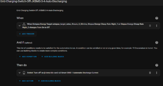
So I found a way to make good use of the Auto-Discharge function that the code provides - previously as reported here before, switching on the function would totally stop discharge: so I have by default switched all the Auto settings off.
However, I find that whenever a charge (Octopus Agile automation active) request from the grid is active for the 1st string, the charging power comes not only from the grid but also from the second string - which sort of defeats the objective of benefiting from cheap tariff offered by my supplier (Octopus).

So what I did to remedy this was to set an Automation to toggle the Auto-Discharge on when charging from the grid and turn it off when charging is completed - this works perfectly.

1718101604345.png

1718101677839.png
I previously did the automation to switch off charging on the second string to remedy this, it kept tripping off the battery breaker switch, not sure what logic is responsible for the over-current surge that might be tripping the breaker switch.

# What I did notice though is that; with the Auto-Discharge switching - it is gradual before the charging stops, but with the switching off charge option, it's pretty much immediate which probably is responsible for the surge produced.

Just wanted to share with others who might have a similar setup......
 
Just checked the forum, hell yeah, the system was so stable I even forgot to check this post/forum.

I even forgot your request of my voltage readings due to your software solving this issue already.


Yep, all entities.


Mode 2.

@chaosnature

I read your DM, sorry I was not able to respond in a timely manner. I take it you already have worked it out based on pages added in this thread.

Im happy to see the continous support and development of this project.

More power to all of you.
@widget4145 Did you upgraded your JK Inverter BMSes to 15.17?
Which firmware version do you have on your BMSes?
How long is your CAN and RS485 cables?
Still fighting with RS485 connection. I suspect strong EMI from my inverter and this may be problem with unstable connections.
 
Last edited:
The RS485 standard recommends 120 ohm resistors on the start and end of the daisy chain run. For a single Inverter to battery run this means 120ohm resistors between A and B on both ends. This may help with interference from EMI as would using the GND wire in the cable.
 
The RS485 standard recommends 120 ohm resistors on the start and end of the daisy chain run. For a single Inverter to battery run this means 120ohm resistors between A and B on both ends. This may help with interference from EMI as would using the GND wire in the cable.
With or without ground wire is exactly the same. Will try 120 ohm resistors.
 

diy solar

diy solar
Back
Top