


You are using an out of date browser. It may not display this or other websites correctly.
You should upgrade or use an alternative browser.
You should upgrade or use an alternative browser.
JK-BMS-CAN with new Cut-Off Charging Logic (open-source)
- Thread starter Sleeper85
- Start date
@Sleeper85 Do you plan to expand BLE variant for all the functions/entities of RS485 version for JK PB BMS series? Love the stability of it ")
Also ordered good communication shielded cables for CAN and RS485 and will fight more with RS485 communication.
Also ordered good communication shielded cables for CAN and RS485 and will fight more with RS485 communication.
@Sleeper85,
I am using the wired version for JK PB series.
Currently i have just one BMS connected with the address 00 (master) to the ESP. For example if i am switching on the discharge switch (the one for BMS not CAN Discharge) from HA, after a few seconds is turning back off and i don't see the change in the JK App on the phone. But if i change in the App the switch in HA is changing and stays.
I have the same problem with all switches in "Controls " except the combine one "smartbms JK-BMS 1 Combine enabled"
What would be the fix for that?
@widget4145 You can switch on and off the discharge switch and see the change in the APP, or any other function from "Controls"?
How did you have set for addresses for all 7 BMS's. Starting from 00 to 06 or from 01 to 07?
Attachments
@virus100b Wired version switches are read only so just represent status of the BMS switch but you cannot change it from HA.
@widget4145 is using mode 2 so his config will be 01 to 07 and this is the only way for ESP to gather all informations from BMSes
@widget4145 is using mode 2 so his config will be 01 to 07 and this is the only way for ESP to gather all informations from BMSes
Sleeper85
Sunday handyman
- Joined
- Nov 28, 2022
- Messages
- 503
@virus100b @cinusik
Concerning the RS485 connection to the JK-BMS PB series, my project is based on the component developed by @txubelaxu. If you have any questions or problems regarding BMS sensors we can discuss them in the discussion below.

 github.com
Concerning the BLE connection to the JK-BMS PB series it is with the syssi component.
Concerning the RS485 connection to the JK-BMS PB series, my project is based on the component developed by @txubelaxu. If you have any questions or problems regarding BMS sensors we can discuss them in the discussion below.
JK-BMS-PB RS485 CAN BUS · txubelaxu esphome-jk-bms · Discussion #8
Hi, First of all, thank you for this new component. I'm integrating your code with my JK-BMS-CAN project. The person currently testing the code in development has 7x JK-BMS-PB and was already using...
github.com
Concerning the BLE connection to the JK-BMS PB series it is with the syssi component.
Thank you for clarifying.@virus100b Wired version switches are read only so just represent status of the BMS switch but you cannot change it from HA.
@widget4145 is using mode 2 so his config will be 01 to 07 and this is the only way for ESP to gather all informations from BMSes
I also want to use Mode 2 as i will install another 16 cells pack and i want to let ESP to control the CAN comm.with inverter.
For mode 2 do i need to change addresses in the code
"bms_rs485_address: '0x00' # BMS 1 DIP switch" starting from 01 or i can let this like that and ESP will just skip BMS1 and will start from BMS2 as this will have address 01?
I don't have second BMS yet to test but i want to be prepared.
I have the option to just use BMS in parallel function but i really like the functions implemented for JK B2A type BMS of @Sleeper85 and @MrPablo (
thank you again for your work) which i am using flawless for more than 4 months now and i just want to continue to use their logic with the newer JKPB Type BMSSleeper85
Sunday handyman
- Joined
- Nov 28, 2022
- Messages
- 503
For mode 2 do i need to change addresses in the code
"bms_rs485_address: '0x00' # BMS 1 DIP switch" starting from 01 or i can let this like that and ESP will just skip BMS1 and will start from BMS2 as this will have address 01 ?
Yes you must modify your YAML, it must correspond exactly to the DIP switches.
After testing this solution few days weird things happened and I do not understand why. When there was enough solar power and battery power SmartBMS switched my Growatt SPF 5000 ES to Solar/Grid mode from Solar/Battery mode. So 500W load was using grid and in the same time battery was charged 4000W. Can you explain logic behind this? It is intentionally programmed? I saw this behavior at balancing state which is perfectly OK allowing balance without using batteries. But why this happened in the morning during Bulk charging state? All the automatic charge voltage, current and discharge are turned off. That's weird for me.
Last edited:
Sleeper85
Sunday handyman
- Joined
- Nov 28, 2022
- Messages
- 503
After testing this solution few days weird things happened and I do not understand why. When there was enough solar power and battery power SmartBMS switched my Growatt SPF 5000 ES to Solar/Grid mode from Solar/Battery mode. So 500W load was using grid and in the same time battery was charged 4000W. Can you explain logic behind this? It is intentionally programmed? I saw this behavior at balancing state which is perfectly OK allowing balance without using batteries. But why this happened in the morning during Bulk charging state? All the automatic charge voltage, current and discharge are turned off. That's weird for me.
The CAN bus simply communicates information about charge, voltage, current, soc, soh, alarms, warning, etc. There is nothing in the code that could change the operating mode of an inverter, however each inverter reacts differently to the information it receives from the CAN bus. This is the case for example with the 100% SoC, some inverters stop charging when the SoC is at 100% and no longer respect the requested charging voltage, this is why 100% is transmitted at the end of the Bulk/Absorption phase only. So we need to understand why your inverter reacted like that?
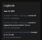
What would be the reason that smartbms is reporting wrong Min/Max Cells Voltage and Temperatures?
This error send the alarm errors seen on logs:
[16:42:31][D][jk_rs485_sniffer:330]: SCANNING TO DISCOVER...0x03
[16:42:32][D][text_sensor:064]: 'smartbms Smart BMS 1 Charging Instruction': Sending state 'Stop'
[16:42:32][D][text_sensor:064]: 'smartbms Smart BMS 1 Alarm': Sending state 'OVP'
[16:42:32][D][sensor:094]: 'smartbms Smart BMS 1 Requested Discharge Voltage': Sending state 0.00000 V with 1 decimals of accuracy
[16:42:32][D][text_sensor:064]: 'smartbms Smart BMS 1 Warning': Sending state 'UTP'
[16:42:32][main:469]: Charge Status : Alarm
[16:42:32][D][text_sensor:064]: 'smartbms Smart BMS 1 Charging Status': Sending state 'Alarm'
[16:42:32][D][sensor:094]: 'smartbms Smart BMS 1 Auto Charge Voltage': Sending state 55.40000 V with 1 decimals of accuracy
[16:42:32][D][jk_rs485_sniffer:330]: SCANNING TO DISCOVER...0x04
[16:42:32][D][jk_rs485_sniffer:330]: SCANNING TO DISCOVER...0x05
[16:42:33][D][text_sensor:064]: 'smartbms Smart BMS 1 Charging Instruction': Sending state 'Stop'
[16:42:33][D][text_sensor:064]: 'smartbms Smart BMS 1 Alarm': Sending state 'OVP'
[16:42:33][D][sensor:094]: 'smartbms Smart BMS 1 Requested Charge Current': Sending state 0.00000 A with 1 decimals of accuracy
[16:42:33][D][text_sensor:064]: 'smartbms Smart BMS 1 Warning': Sending state 'UTP'
[16:42:33][main:469]: Charge Status : Alarm
[16:42:33][D][text_sensor:064]: 'smartbms Smart BMS 1 Charging Status': Sending state 'Alarm'
[16:42:33][D][sensor:094]: 'smartbms Smart BMS 1 Auto Charge Voltage': Sending state 55.40000 V with 1 decimals of accuracy
[16:42:33][D][jk_rs485_sniffer:330]: SCANNING TO DISCOVER...0x06
Sleeper85
Sunday handyman
- Joined
- Nov 28, 2022
- Messages
- 503
It seems that you are having the same problem as txubelaxu, it is the default values of the sensors that are displayed when no BMS is combined. We can continue on the subject below:What would be the reason that smartbms is reporting wrong Min/Max Cells Voltage and Temperatures?
This error send the alarm errors seen on logs:
[16:42:31][D][jk_rs485_sniffer:330]: SCANNING TO DISCOVER...0x03
[16:42:32][D][text_sensor:064]: 'smartbms Smart BMS 1 Charging Instruction': Sending state 'Stop'
[16:42:32][D][text_sensor:064]: 'smartbms Smart BMS 1 Alarm': Sending state 'OVP'
[16:42:32][D][sensor:094]: 'smartbms Smart BMS 1 Requested Discharge Voltage': Sending state 0.00000 V with 1 decimals of accuracy
[16:42:32][D][text_sensor:064]: 'smartbms Smart BMS 1 Warning': Sending state 'UTP'
[16:42:32][main:469]: Charge Status : Alarm
[16:42:32][D][text_sensor:064]: 'smartbms Smart BMS 1 Charging Status': Sending state 'Alarm'
[16:42:32][D][sensor:094]: 'smartbms Smart BMS 1 Auto Charge Voltage': Sending state 55.40000 V with 1 decimals of accuracy
[16:42:32][D][jk_rs485_sniffer:330]: SCANNING TO DISCOVER...0x04
[16:42:32][D][jk_rs485_sniffer:330]: SCANNING TO DISCOVER...0x05
[16:42:33][D][text_sensor:064]: 'smartbms Smart BMS 1 Charging Instruction': Sending state 'Stop'
[16:42:33][D][text_sensor:064]: 'smartbms Smart BMS 1 Alarm': Sending state 'OVP'
[16:42:33][D][sensor:094]: 'smartbms Smart BMS 1 Requested Charge Current': Sending state 0.00000 A with 1 decimals of accuracy
[16:42:33][D][text_sensor:064]: 'smartbms Smart BMS 1 Warning': Sending state 'UTP'
[16:42:33][main:469]: Charge Status : Alarm
[16:42:33][D][text_sensor:064]: 'smartbms Smart BMS 1 Charging Status': Sending state 'Alarm'
[16:42:33][D][sensor:094]: 'smartbms Smart BMS 1 Auto Charge Voltage': Sending state 55.40000 V with 1 decimals of accuracy
[16:42:33][D][jk_rs485_sniffer:330]: SCANNING TO DISCOVER...0x06
View attachment 222036
DEV: some "by default" values wrong for LiFePo4 · Issue #53 · Sleeper85/esphome-jk-bms-can
Some "by default" values are wrong for LiFePo4 batteries:
github.com
So, it looks like Growatt programmed inverter logic then.The CAN bus simply communicates information about charge, voltage, current, soc, soh, alarms, warning, etc. There is nothing in the code that could change the operating mode of an inverter, however each inverter reacts differently to the information it receives from the CAN bus. This is the case for example with the 100% SoC, some inverters stop charging when the SoC is at 100% and no longer respect the requested charging voltage, this is why 100% is transmitted at the end of the Bulk/Absorption phase only. So we need to understand why your inverter reacted like that?
My inverter mode was set to SBU (Solar/Battery/Utility) - will change mode to SOL (Solar first) and will observe if the same things will happen again.
EDIT: OK, cannot change to SOL as in the SOL mode as soon as PV is not available inverter is switching to grid mode. So will test more to find out what is causing this unwanted switching to grid mode.
Last edited:
widget4145
New Member
Yes, they are all at 15.17.@widget4145 Did you upgraded your JK Inverter BMSes to 15.17?
Which firmware version do you have on your BMSes?
How long is your CAN and RS485 cables?
Still fighting with RS485 connection. I suspect strong EMI from my inverter and this may be problem with unstable connections.
CAN around 2 meters, RS485, the longest one is around 5 meters, and ran along with AC wires.
Found the cause of my RS485 connection problems but for now I have no idea how to fix it.
As soon as I turn off solar panels from my inverter using isolation switch all the communication immediately starting to work without any problems. When I turn them back on than after few seconds RS485 communication is gone or very unstable, causing also ESP restart.
I suspect strong interferences from my PV cabling is going thru inverter to batteries causing RS485 connection mess. Few meters of the PV cables is routed along AC cables and I think, it may be the problem or the MPPT in inverter is such a big bad noise generator. What do you think?
Last edited:
This is some amazing work, looks like a lot in progress still, and I am just wondering if there is a consensus on best components to use to put this together. I have not bought anything yet, maybe the first or 2nd post on this thread could be updated with a link to "latest/greatest" components.
This is my plan (hoping to buy all this in the next month):
1 EG4 18KPV (possibly 2 in future, or 2 Growatt 10kHU if they pan out)
2x EVE 16S packs (possibly 3-4 future)
Hoping for wire reduction using BLE, could wire RS485
Have Home Assistant VM, hoping to integrate with Solar Assistant to automate things like well pumps after 100% SOC reached.
Which JK model is best, ESP32 models... etc.
Likely that the galvanic isolation in the inverter ttl to rs485 circuitry is faulty or missing.Found the cause of my RS485 connection problems but for now I have no idea how to fix it.
As soon as I turn off solar panels from my inverter using isolation switch all the communication immediately starting to work without any problems. When I turn them back on than after few seconds RS485 communication is gone or very unstable, causing also ESP restart.
I suspect strong interferences from my PV cabling is going thru inverter to batteries causing RS485 connection mess. Few meters of the PV cables is routed along AC cables and I think, it may be the problem or the MPPT in inverter is such a big bad noise generator. What do you think?
@kommando I do not use RS485 connection to inverter for now. For now for testing it is just ESP Atom connected to RS485 of one of two batteries with JK BMSes.Likely that the galvanic isolation in the inverter ttl to rs485 circuitry is faulty or missing.
Try this, turn on the PV but turn off the charging only on the battery BMS you have the RS485 connection with, this may isolate the interference to the PV charging.@kommando I do not use RS485 connection to inverter for now. For now for testing it is just ESP Atom connected to RS485 of one of two batteries with JK BMSes.
Sleeper85
Sunday handyman
- Joined
- Nov 28, 2022
- Messages
- 503
This is some amazing work, looks like a lot in progress still, and I am just wondering if there is a consensus on best components to use to put this together. I have not bought anything yet, maybe the first or 2nd post on this thread could be updated with a link to "latest/greatest" components.
This is my plan (hoping to buy all this in the next month):
1 EG4 18KPV (possibly 2 in future, or 2 Growatt 10kHU if they pan out)
2x EVE 16S packs (possibly 3-4 future)
Hoping for wire reduction using BLE, could wire RS485
Have Home Assistant VM, hoping to integrate with Solar Assistant to automate things like well pumps after 100% SOC reached.
Which JK model is best, ESP32 models... etc.
Hi,
If you have to buy everything...
- Atom S3 Lite or Atom S3 (display)
- Atomic CAN bus base
- New JK-BMS PB series
DEV README
DEV JK-BMS-PB-CAN README (contains the list of components)
@cinusik @virus100b
The RS485 board which is proposed in this README (draft) is the one used by @txubelaxu who developed the RS485 component for the new JK-BMS PB. It's definitely not the best board. With PVbrain2 we use the board below which has galvanic isolation but it has not yet been tested with the component from @txubelaxu, this board does not need TALK PIN.
RS485 board High Speed Dual version
Last edited:
Tried as you advised, no change. Even turning off MCCB to batteries did not helped so it looks like strong interference?Try this, turn on the PV but turn off the charging only on the battery BMS you have the RS485 connection with, this may isolate the interference to the PV charging.
Last edited:
I do not think, that galvanic separation will help in my case because I tried on MCCB disconnected batteries and connection problems are still there so as stated above I suspect very strong interference from my PV panels/cabling/MPPT.@cinusik @virus100b
The RS485 board which is proposed in this README (draft) is the one used by @txubelaxu who developed the RS485 component for the new JK-BMS PB. It's definitely not the best board. With PVbrain2 we use the board below which has galvanic isolation but it has not yet been tested with the component from @txubelaxu, this board does not need TALK PIN.
RS485 board High Speed Dual version
@Sleeper85 So now I know that your SmartBMS is working perfectly, even with @txubelaxu board with talk pin. There is something wrong with my PV system and I'll investigate this further. I'll start with PV cabling separation from AC cabling.
Last edited:
Sleeper85
Sunday handyman
- Joined
- Nov 28, 2022
- Messages
- 503
I added an alternative board (isolated without TALK PIN) in the README for this new solution with the JK-BMS PB series and I also asked @txubelaxu if he wanted to test this board.
README JK-BMS-PB-CAN solution
README JK-BMS-PB-CAN solution
Yes does look like the inverter is transmitting a large amount of interference, now is it a fault unique to your inverter or part of the design ?Tried as you advised, no change. Even turning off MCCB to batteries did not helped so it looks like strong interference?
One last trick is to only connect the 2 A B wires and have a break in the other 6 wires and then only on one end connect the cable shield to an earth.
Sleeper85
Sunday handyman
- Joined
- Nov 28, 2022
- Messages
- 503
@virus100b @cinusik @kommando @silverstone @chaosnature
I'm updating the list of users with their config.
Can you complete the points below please?
I'm updating the list of users with their config.
Can you complete the points below please?
- Inverter brand:
- Inverter model:
- Inverter Battery mode:
- BMS model:
- BMS link: BLE / UART / RS485
- ESP32 board:
- CAN name:
- CAN protocol:
- CAN board:
- Multi-BMS: yes/no
- Remarks:
Last edited:
Try to use a ferrite ring and wrap the 485 cable twice through the ring. Deye is supplying with the inverter 2 ferite Rings. One for Battery cables and one for BMS cable.Tried as you advised, no change. Even turning off MCCB to batteries did not helped so it looks like strong interference?
Similar threads
- Replies
- 27
- Views
- 741
- Replies
- 8
- Views
- 859
- Replies
- 19
- Views
- 1K
- Replies
- 4
- Views
- 725