diy solar

diy solar

JK-BMS-CAN with new Cut-Off Charging Logic (open-source)

Yes does look like the inverter is transmitting a large amount of interference, now is it a fault unique to your inverter or part of the design ?

One last trick is to only connect the 2 A B wires and have a break in the other 6 wires and then only on one end connect the cable shield to an earth.
OK, finally got it working :) Changed cable to good shielded RS465, connected A, B, GND and one end of shield to Earth. Since 15 minutes.
@Sleeper85 During the today tests I found missing piece of logic to your SmartBMS. When I turned off charging on one BMS, requested charge current did not changed. It is not a problem with 280Ah batteries and single inverter capable of 100Amps charging but when you have multiple inverters like 3 capable of 300A charging to one battery that may introduce some risks. I know that BMS protection should not allow such high charging current but in case BMS will fail there is potential to make some fire ;)

EDIT: After 25minutes it restarted without particular reason :( I give up. But it was the longest time I was able to run it without RS485 instability.

EDIT2: It restarted at balancing state, at this moment my inverter switched to grid mode. During this switch ESP restarted. Turned off grid to inverter and will be doing more testing.
 
Last edited:
OK, finally got it working :) Changed cable to good shielded RS465, connected A, B, GND and one end of shield to Earth. Since 15 minutes.
@Sleeper85 During the today tests I found missing piece of logic to your SmartBMS. When I turned off charging on one BMS, requested charge current did not changed. It is not a problem with 280Ah batteries and single inverter capable of 100Amps charging but when you have multiple inverters like 3 capable of 300A charging to one battery that may introduce some risks. I know that BMS protection should not allow such high charging current but in case BMS will fail there is potential to make some fire ;)

EDIT: After 25minutes it restarted without particular reason :( I give up. But it was the longest time I was able to run it without RS485 instability.

EDIT2: It restarted at balancing state, at this moment my inverter switched to grid mode. During this switch ESP restarted. Turned off grid to inverter and will be doing more testing.

Which board?
Do you use the web server?
How many BMS?

The refresh intervals below work with ESP32-S3 but it may be necessary to increase them for classic ESP32.
This also depends on the number of BMS.

The Web server is a component that takes up a lot of resources and can have a negative impact.

YAML:
bms_update_interval: '3s' # going below '3s' can cause problems
bms_combine_interval: '1s'
smartbms_update_interval: '1s'
Exactly this values - not changed them.
Board is AtomS3, no web server just HA, 2 PB BMSes.
 
Getting more interested in the multi BMS setup at it progresses but why is it needed with the JK PB BMS (inverter bms)? Thought they can simply chain together and connect to inverter without this custom solution.
 
Getting more interested in the multi BMS setup at it progresses but why is it needed with the JK PB BMS (inverter bms)? Thought they can simply chain together and connect to inverter without this custom solution.
Most of inverters turn off charging as soon as JK Inverter BMS reports 100% SOC giving no time for cells to Absorb and Balance. That is why this solution is great.
 
Getting more interested in the multi BMS setup at it progresses but why is it needed with the JK PB BMS (inverter bms)? Thought they can simply chain together and connect to inverter without this custom solution.
The SMA Sunny Island, well at least the SI5048, does not suffer from the Inverter stopping charging at calculated 100%, it continues charging until the RCV on one cell is reached. Other inverters stop charging at the calculated 100% so this solution acts as a filter in the middle and stops this soft 100% getting to the Inverter and so it continues charging.

Even with an Inverter like the SMA the JK SOC cal is inaccurate especially if you are PV charging only and are not getting to RCV on a regular basis. So again it can filter out wrong SOC such as 10% when its really at 20%.
 
Getting more interested in the multi BMS setup at it progresses but why is it needed with the JK PB BMS (inverter bms)? Thought they can simply chain together and connect to inverter without this custom solution.

This is correct, JK-BMS PB series does not need this project because it supports several different CAN protocols including PYLON and Victron.

It was @widget4145 who asked me first because he liked the inverter_offset function which is useful with Deye.
With this project, the new cutoff charging logic is certainly better than what JK does.
There are also the AutoCVL, AutoDCL, AutoCCL functions from @MrPablo
In short, with JK-PB both solutions are possible.

The best would be to have the opinion of @cinusik and @virus100b
Why not use the can bus integrated into the JK-PB?

Edit: as @kommando just said, there are a few small functions that can help depending on the inverter model.
 
Last edited:
This is correct, JK-BMS PB series does not need this project because it supports several different CAN protocols including PYLON and Victron.

It was @widget4145 who asked me first because he liked the inverter_offset function which is useful with Deye.
With this project, the new cutoff charging logic is certainly better than what JK does.
There are also the AutoCVL, AutoDCL, AutoCCL functions from @MrPablo
In short, with JK-PB both solutions are possible.

The best would be to have the opinion of @cinusik and @virus100b
Why not use the can bus integrated into the JK-PB?

Edit: as @kommando just said, there are a few small functions that can help depending on the inverter model.
Thanks for the reply. I’ll sit wait for the non-inverter JK multi BMS solution, singlle BMS works great with Atom Lite. Almost made the jump to new inverter series but both boxes were damaged in shipping.
 
Thanks for the reply. I’ll sit wait for the non-inverter JK multi BMS solution, singlle BMS works great with Atom Lite. Almost made the jump to new inverter series but both boxes were damaged in shipping.

The multi-BMS version in the dev branch works for both JK-BMS models.

Please note, this is a multi-BMS solution with a single ESP32.

With the new JK-PB series only one RS485 connection is required with max 16 BMS.

With the old JK-B series all BMS are connected to the ESP32.

An ESP32 supports max 3 UARTs and 3 BLE connections, it can be a mix of the two. I haven't yet been able to carry out many tests on my own but it is certain that the more BMS there are to connect, the more the limits of the classic ESP32 will be reached. ESP32-S3 or Atom S3 are preferred but I think a classic ESP32 should work well with 2 BMS.

The PVbrain2 PCB with ESP32-S3 supports 11 UARTs.
 
@cinusik

The following conditions must be met for the BMS to be combined.
If one of these conditions becomes invalid, the BMS is decombined.
  • BMS switch charging ON
  • BMS switch discharging ON
  • BMS no errors
  • Combined switch ON
Attention ! with the new JK-PB series and the RS485 component from @txubelaxu the BMS switches (in HA) are currently 'read only' and must be controlled from the JK application.
 
The best would be to have the opinion of @cinusik and @virus100b
Why not use the can bus integrated into the JK-PB?
The answer to your question is simple. I just love the charging logic of this project and i want to have more control of BMS.
I am away from home with my work sometimes more than a month and i like to see and control the battery and BMS parameters.
Currently i have just 1 battery pack and i am not running PB JK Bms. I am still on old JK, but just to be able to test new PB code, i have the PB connected with balance wires in parallel with old JK and with balance function OFF and no CAN connected. The old JK in use is connected to can port of Deye and runs flawless for over 4 months now. Once arrived home i will add another battery pack, remove the old JK and use two JK PB.

The only function i miss from old JK is the ability to control the BMS switches, function which is just read only for now on PB series.
 
Thanks for the reply. I’ll sit wait for the non-inverter JK multi BMS solution, single BMS works great with Atom Lite. Almost made the jump to new inverter series but both boxes were damaged in shipping.
I think the new inverter type BMS has another advantage, the possibility to add your custom power cables. The ones that comes with old JK (B series) are soldered on PCB and i find them underrated for the max current that BMS can support. I am running my JK B series BMS with max 140A and they get pretty hot.
The new type PB series comes with a screw terminal which give me the possibility to install 2 x 25mm2 cables for power cables.
 
This is some amazing work, looks like a lot in progress still, and I am just wondering if there is a consensus on best components to use to put this together. I have not bought anything yet, maybe the first or 2nd post on this thread could be updated with a link to "latest/greatest" components.

This is my plan (hoping to buy all this in the next month):
1 EG4 18KPV (possibly 2 in future, or 2 Growatt 10kHU if they pan out)
2x EVE 16S packs (possibly 3-4 future)
Hoping for wire reduction using BLE, could wire RS485

Have Home Assistant VM, hoping to integrate with Solar Assistant to automate things like well pumps after 100% SOC reached.

Which JK model is best, ESP32 models... etc.
Use Google picture to search for :

1718748785770.png
OR
1718748836232.png

this is my config and it works great and is stable on BLE


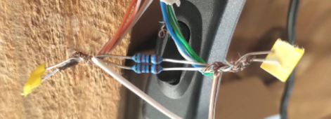
# And dont forget the 120 ohms resistors like i did - If required, depending on your Inverter
1718748956357.png
 
  • Inverter brand: Solis / Sofar
  • Inverter model: SOL-3K-RHI-48ES / HYD 3600-ES
  • Inverter Battery mode: DIY Growatt GBLI5001 Converted.
  • BMS model: JK-PB2A16S15P / JK-B2A24S15P
  • BMS link: BLE
  • ESP32 board: Atom S3 Lite / Screen
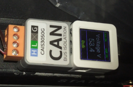
  • CAN name: CAN Bus Isolation - CAIS3050G
  • CAN protocol: SMA / Pylontech
  • CAN board:
  • CAN Bus Isolation - CAIS3050G
  • Multi-BMS: no
  • Remarks: Prefared over original BMS Manufacture's Management System

Thank You...
 
The multi-BMS version in the dev branch works for both JK-BMS models.

Please note, this is a multi-BMS solution with a single ESP32.

With the new JK-PB series only one RS485 connection is required with max 16 BMS.

With the old JK-B series all BMS are connected to the ESP32.

An ESP32 supports max 3 UARTs and 3 BLE connections, it can be a mix of the two. I haven't yet been able to carry out many tests on my own but it is certain that the more BMS there are to connect, the more the limits of the classic ESP32 will be reached. ESP32-S3 or Atom S3 are preferred but I think a classic ESP32 should work well with 2 BMS.

The PVbrain2 PCB with ESP32-S3 supports 11 UARTs.
Thanks, have plenty of classic ESP32 laying around and may give it a shot with non-inverter BMS until my damaged ones re-ship. Have to look for CAN bus as only have some MCP2515 around at the moment. Not going to disconnect my working Atom Lite as it’s running the single BMS system now unless you think it can run it (non-S model).
 
Thanks, have plenty of classic ESP32 laying around and may give it a shot with non-inverter BMS until my damaged ones re-ship. Have to look for CAN bus as only have some MCP2515 around at the moment. Not going to disconnect my working Atom Lite as it’s running the single BMS system now unless you think it can run it (non-S model).

FYI MCP2515 is supported. You can use the classic ESP32 which is equal to Atom Lite (ESP32-S3 / Atom S3 are more powerful). I don't remember what config you have, I know you have several different brand inverters. What you need to know is that with this new version it is possible to create several different canbus so that several different brand inverters can communicate with your batteries at the same time.
 
@Sleeper85
  • Inverter brand: Growatt
  • Inverter model: SPF 5000 ES
  • Inverter Battery mode: SBU
  • BMS model: 2x JK PB2A16S20P
  • BMS link: BLE
  • ESP32 board: M5Stack AtomS3
  • CAN name: Pylon 1.2
  • CAN protocol: Pylon / Pylon 1.2
  • CAN board: M5Stack CAN Unit ca-is3050g
  • Multi-BMS: yes
  • Remarks: Best solution for the incomplete/wrong protocols implementation on JK Inverter BMSes and some inverters.
  • Wishes:
    1. I wish that all the entities from JK PB RS485 version will be implemented to BLE version to make it more JK PB friendly ;)
    2. I wish that multi bms logic will be updated - so if you turn off charging on one of the BMSes than it should subtract requested charge current from smart bms
    3. I wish some way to expand the BLE system to more than 3 devices - maybe some ESP32 interconnections?
      Let's say we have 6 JK PB BMSes - so 2 ESP32 will be used, one of the ESP32 will be CAN connected to inverter and 2 ESP32 should talk to each other.
 
Last edited:
Not using the Sleeper85 solution as yet but this is my current setup using JK Canbus closed loop

  • Inverter brand: SMA
  • Inverter model: Sunny Island SI5048 50htz
  • Inverter Battery mode: Off grid
  • BMS model: 2x JK PB2A16S20P
  • BMS link: JK RS485 Master/Slave DIP 0/DIP 1
  • ESP32 board: none
  • CAN name: fss-connectingbat-ti-en-20w (JK used the odd FSS label as this is the SMA PDF doc ref, why the obscure ref instead of SMA ?)
  • CAN protocol: SMA Canbus for 6.0/8.0H-11
  • CAN board: Using internal JK Canbus
  • Multi-BMS: yes
I do not get the inverter stopping charge when the calculated SOC is 100%, the SI's carry on charging until the required 55.2V is achieved. The SI's then curtail PV production to maintain the 55.2V for 1 hr and then the JK drops the required voltage to float of 53.2V as per my settings which the SI's respond to and stop charging until 53.2V is achieved and then recommence balanced curtailment.

As the SOC is badly calculated by the JK and I only use PV to charge the batteries I am finding that the SOC gets worse if the 55.2V is not achieved on a regular basis. So once the Sleeper85 solution is more polished I plan to change and use its interventions to keep the SOC more accurate. I can afford to wait as I have a working solution and its summer.
 
I wish that multi bms logic will be updated - so if you turn off charging on one of the BMSes than it should subtract requested charge current from smart bms

This is normally already the case if you receive BMS information from BLE. See the answer I posted yesterday.

 
  • Inverter brand: Solis / Sofar
  • Inverter model: SOL-3K-RHI-48ES / HYD 3600-ES
  • Inverter Battery mode: DIY Growatt GBLI5001 Converted.
  • BMS model: JK-PB2A16S15P / JK-B2A24S15P
  • BMS link: BLE
  • ESP32 board: Atom S3 Lite / Screen
  • CAN name: CAN Bus Isolation - CAIS3050G
  • CAN protocol: SMA / Pylontech
  • CAN board:
  • CAN Bus Isolation - CAIS3050G
  • Multi-BMS: no
  • Remarks: Prefared over original BMS Manufacture's Management System

Thank You...

Thanks for the response, I can add your two systems to the list.

Can you confirm for me that with Solis you use the 'AoBo' battery type with the 'SMA' protocol?

With Sofar, do you need to select a special battery mode in your inverter? Are you using the 'PYLON 1.2' or 'PYLON +' protocol?

Solis is connected to an Atom S3 Lite supervising via BLE two Li-ion battery packs (2x JK-PB*), is this correct?

Sofar is connected to an Atom S3 (display) supervising via BLE two Li-ion battery packs (2x JK-B), is this correct?

On which inverter did you have to add the 120 Ohm resistor?
 
@Sleeper85
  • Inverter brand: Growatt
  • Inverter model: SPF 5000 ES
  • Inverter Battery mode: SBU
  • BMS model: 2x JK PB2A16S20P
  • BMS link: BLE
  • ESP32 board: M5Stack AtomS3
  • CAN name: Pylon 1.2
  • CAN protocol: Pylon / Pylon 1.2
  • CAN board: M5Stack CAN Unit ca-is3050g
  • Multi-BMS: yes
  • Remarks: Best solution for the incomplete/wrong protocols implementation on JK Inverter BMSes and some inverters.
  • Wishes:
    1. I wish that all the entities from JK PB RS485 version will be implemented to BLE version to make it more JK PB friendly ;)
    2. I wish that multi bms logic will be updated - so if you turn off charging on one of the BMSes than it should subtract requested charge current from smart bms
    3. I wish some way to expand the BLE system to more than 3 devices - maybe some ESP32 interconnections?
      Let's say we have 6 JK PB BMSes - so 2 ESP32 will be used, one of the ESP32 will be CAN connected to inverter and 2 ESP32 should talk to each other.

Thanks for the response, I can add your system to the list.

In your inverter, have you chosen 'CAN L52' as the battery type ?
 
FYI MCP2515 is supported. You can use the classic ESP32 which is equal to Atom Lite (ESP32-S3 / Atom S3 are more powerful). I don't remember what config you have, I know you have several different brand inverters. What you need to know is that with this new version it is possible to create several different canbus so that several different brand inverters can communicate with your batteries at the same time.
If this works with Atom lite/Can adapter, id rather give that a shot as it’s cleaner to build compared to esp32 with mcp2515. I’ll just take my system offline for a few hours, split my pack from 2p16s to two 1p16s and add in another non-inverter JK.
 

diy solar

diy solar
Back
Top