diy solar

diy solar

BMS goes Kaboom!

salaxi54

New Member
Joined
Jun 24, 2024
Messages
22
Location
Greece
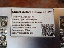
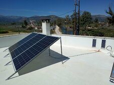
Alrighty, so i set up a rather small system, which consists of 3x340W panels, an Easun SPH-3K (3.2Kw) inverter, a JK-B2A8S20P-H BMS, and an 8x3.2-cell Lithium battery. The BMS was bought second-hand from the same fella i got the battery, and had been checked and set by him, reported ok.
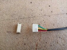
So, i assembled everything, and then came the moment of hooking up the battery and BMS. Things started to look bad the moment i attempted to plug the BMS switch cable to the pcb. Its' socket came right off, without the use of force, as if it were just adhered there temporarily.
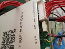
I thought to myself, well, that's no big deal, lemme just solder the cables' pins directly on the pcb. Which i did, and after bolting the negative part of the BMS to the battery, the thing went on, before i even completed the connection of the positive side. My guess is that once the negative pole was connected, there must've been a circuit that completed 7 out of the 8 cells until i connect the last cable.
Without further ado, i ran the app, and verified that i had a status of 7 out of the 8 cells, before plugging the positive pole.
Now, please excuse me if everything sounds stupid, but this is my first attempt on anything solar! I've not much idea on terminology, theory and whatsoever.
Anyway, i guessed everything was now normal, and proceeded to plug the positive terminal. The inverter and everything else was shut at the time of course.
Less than a minute after connection, there was a large bang sound, sparks and flames! All coming from the BMS (scared the sh** out of me).
That only lasted for seconds, and i rushed into disconnecting everything. My planning on this system is to have an independent 1Kw system for the needs of my small lab (mancave). I've been a DIYer all my life, and wanted to experiment on something small before going into something bigger in the future.
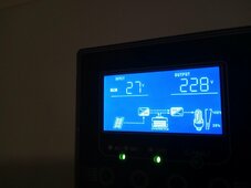
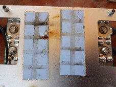
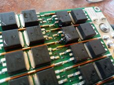
The whole whatchamacallit was installed by yours trully, and i'm attaching some pics before starting to ask questions.Panels.jpgDisplay.jpgBMS 1.jpgBMS 2.jpgBMS 3.jpg
 
You can see that some of the MOSFETs were burnt, and i thought it was only the 2 on the one side of the pcb. But after disassembling the other side, i found 3 more blown up. Now, i have seen videos on YT where other people have had the same issues with JK BMSs, that blew a few MOSFETs but could still operate. Not willing to get this thing connected on the system again, although i went through the process of replacing all 5 of them blown parts. My initial question is: the inverter seems to be able to charge the battery without the BMS being involved. I've seen it on the display, but was not feeling safe to let it operate for more than a few minutes. So, is it ok if i let the inverter do the charging part, without a BMS in the equation? Is there an easy way for me to maybe setup the inverters' menu (if necessary) to handle that? If not, should i go for another BMS, probably same model/specs? I haven't removed the thin cabling from the battery (sensors etc), just in case i can plug the new BMS back on.
Now remember, this is coming from a complete newbie on solar power.
Attached are photos of the socket that came off, and directly-soldered cable.
BMS 4.jpg

BMS 5.jpg
 
My initial question is: the inverter seems to be able to charge the battery without the BMS being involved. I've seen it on the display, but was not feeling safe to let it operate for more than a few minutes. So, is it ok if i let the inverter do the charging part, without a BMS in the equation?
No! That is one of the primary reasons for the bms. It balances the cells during charging, and cuts off charging when a cell voltage gets too high. You risk damaging a cell if you charge without a bms.
 
My initial question is: the inverter seems to be able to charge the battery without the BMS being involved. I've seen it on the display, but was not feeling safe to let it operate for more than a few minutes. So, is it ok if i let the inverter do the charging part, without a BMS in the equation?
This is very risky. Without BMS balancing/constantly monitoring the cell voltage levels there's a good chance you get a "runner" or two as you are charging that are going to spike up in voltage sooner than the rest. So for example most of your cells may be at 3.45V and ones heading to 3.6V and beyond.
 
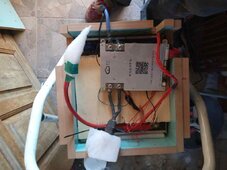
I didn't wire the BMS myself, but the guy who sold me the battery did. I've only a rather missleading pic of it at the moment:

View attachment 224216

That was taken before everything was hooked up.
I don't have that specific model but pretty sure there should be another silicone cable going from that other connector, to match what's happening with the two black cables.

Also those sense leads look they could easily be frayed by the edge of that top cover.
 
I didn't wire the BMS myself, but the guy who sold me the battery did. I've only a rather missleading pic of it at the moment:

View attachment 224216

That was taken before everything was hooked up.
I don't have that specific model but pretty sure there should be another silicone cable going from that other B- connector, to match what's happening with the two black cables.

Also those sense leads look they could easily be frayed by the edge of that top cover.
 
No! That is one of the primary reasons for the bms. It balances the cells during charging, and cuts off charging when a cell voltage gets too high. You risk damaging a cell if you charge without a bms.
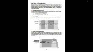
I thought so too, but wanted to make sure before having to do a new purchase... Nevertheless, here's a screenshot of the inverters' manual that got me questioning the need for a BMS:

bms 7.jpg
 
I don't have that specific model but pretty sure there should be another silicone cable going from that other B- connector, to match what's happening with the two black cables.

Also those sense leads look they could easily be frayed by the edge of that top cover.
That "top cover" was just a temporary means of protection while moving the battery around.
 
Ok, so BMS it is i guess.. Is there some sorta guide for properly connecting the BMS, and setting its' parameters up? Only recently moved to the country-side, and there's no tech or merchant in the vicinity to hire/help do this. Would it be a difficult task for me?
BTW, is my thinking of leaving the sensors (thin cables) on for connection to the new BMS correct?
I will try to get a few pics of the cabling asap.
 
From the extent of the damage it looks that the BMS was connected across the cell pack.
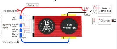
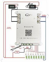
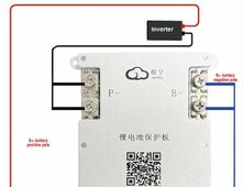
Replace the BMS and balance leads. The BMS is connected in series with the cells negative path, B- to the most negative cell, P- to loads and chargers. The only positive connection to the BMS is via the balance leads. Wire up the leads and connect the balance lead connector last.
Screenshot_20230720-205506_Chrome~2.jpg
 
Without further ado, i ran the app, and verified that i had a status of 7 out of the 8 cells, before plugging the positive pole.
If you connected battery positive to the BMS, this is why things blew up. That gives you basically a direct short circuit. BMS goes between your loads and your negative pole. Positive goes through fuse to your load.
 
If you connected battery positive to the BMS, this is why things blew up. That gives you basically a direct short circuit. BMS goes between your loads and your negative pole. Positive goes through fuse to your load.
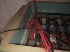
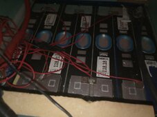
Yup, i guess that's it! Said i was a newb, my fault... Will wait on a new identical BMS now, lesson learnt. By the way, as promised, a couple of pics i took of the battery cabling. Not the clearest view, but the battery is mounted somewhere high, so i would have to bring it down to the floor to get better pics. It was installed there to minimize cable length between it and the inverter. As many of you might've heard, in Europe batteries are supposed to be installed outside the main house, so i put mine in the storage shed.

bat 1.jpg

bat 2.jpg
 
So, another question concerning the BMS; my understanding is that no matter what the initial setup was (by the previous owner), once you run the app for the first time, things -i guess- turn back to factory default, or at least to the apps' default. Is my thinking correct, or does the BMS have a means of saving the parameters anyway? Reason i'm asking is because once the new one arrives, i'm almost certain it will need a fresh setup?
Sorry if all this sounds amateur, but i'd really like to widen my knowledge..
I'll open another thread soon for questions about the rest of the system, and the second system i intend to build soon.
 

As a heads up, I do not believe those are LFP Cells (3.2V per cell), I'm pretty sure they are CATL NCM 117Ah VDA Cells (https://www.aliexpress.us/item/3256806021112060.html) which are 3.7V nominal and have a charge range of 2.5V-4.2V cell. It should also be noted that NCM cells can be very flammable when damaged or abused. Since the cells still have their original GB/T QR code on them, I can tell you a bit more about them if you get a clearer picture of the QR code.
 
Not the first time that this has happened and won’t be the last. I have yet to open a JK box to find any literature. Yes, there’s a QR code to scan, but what if you are in the middle of B.F. nowhere and can’t get a signal. Or if you are like me you rarely mess with a laptop so you’re looking at a little picture on your phone a pinching big to see it better but now you might be missing something. What would it cost for a double sided box size pamphlet with a quick start guide and warnings on one side and diagram on the other? Even Overkill and Daly usually have this.
 
As a heads up, I do not believe those are LFP Cells (3.2V per cell), I'm pretty sure they are CATL NCM 117Ah VDA Cells (https://www.aliexpress.us/item/3256806021112060.html) which are 3.7V nominal and have a charge range of 2.5V-4.2V cell. It should also be noted that NCM cells can be very flammable when damaged or abused. Since the cells still have their original GB/T QR code on them, I can tell you a bit more about them if you get a clearer picture of the QR code.
I mentioned in my initial post them being Lithium, not LiFePo4. But per the seller they're supposed to be Lithium-Ion 3.2, a pack of 118Ah. Nevertheless, your assumption seems correct, and i'll keep the specs from aliexpress, as i believe they will be handy once the new BMS comes in.
 
Not the first time that this has happened and won’t be the last. I have yet to open a JK box to find any literature. Yes, there’s a QR code to scan, but what if you are in the middle of B.F. nowhere and can’t get a signal. Or if you are like me you rarely mess with a laptop so you’re looking at a little picture on your phone a pinching big to see it better but now you might be missing something. What would it cost for a double sided box size pamphlet with a quick start guide and warnings on one side and diagram on the other? Even Overkill and Daly usually have this.
How true! Minor detail, the QR code on the BMS gave me a link to an app that wasn't supported by my android phone. Thus, i had to download a different version of it, which did run.
 
Yes but how do you plan on charging it? Or is it an inverter/charger combo?
It actually is a charging function inverter, but do you suppose it would be better having an external one? Please have a look at my first post, where you can see the inverters' display showing that it was charging the battery.
 

diy solar

diy solar
Back
Top