diy solar

diy solar

Has anyone tried to use SRNE (Modbus ?) communication protocol with MakeskyBlue, PowMR or EASUN SCCs ?

akumd

New Member
Joined
Feb 8, 2024
Messages
32
Location
Sri lanka
I saw in several places that, MakeskyBlue, PowMR or EASUN Solar Charge Controllers are all re-brands of SRNE (or Voltronic) AND they are able to use SRNE Software applications with MakeskyBlue, PowMR or EASUN SCCs.

If this is true, I am guessing one should be able to communicate (read/change settings) with a MakeskyBlue, PowMR or EASUN SCC using SRNE published protocol(MODBUS) in a software application.

Is there any one who tried this ?
 
I'm very much interested in this. The main question is, are these using true modbus protocol?

I have a DEYE SMK 3K and also a EASUN SMH-ii-7k, both came with identical "wifi dongles". I haven't powered up the EASUN yet as I haven't got a battery yet, but I'm pretty sure if both use the same WIFI dongle they should use the same protocol.

The way these dongles work supposedly is they encapsulate Modbus (which is serial) into Solarman5 TCP protocol. There exist various open source libraries that let you use it. For example https://github.com/jmccrohan/pysolarmanv5 and for DEYE this software https://pypi.org/project/deye-controller/

Why am I talking abiut Deye in a thread about ESUN? Because I'm hoping this software can be fairly easily modified to work with EASUN with a wifi dongle.

However if we want to talk directly via Modbus serial, this open source project is a good starting point: https://github.com/cole8888/SRNE-Solar-Charge-Controller-Monitor there is a SRNE modbus manual there and some example software for arduino etc to read some data. Personally I'd much prefer if there was a python example that could be run on a linux PC or a raspberry PI, but this is much better than nothing.

I'm interested in this to be able to have my PC/controller switch charging and source priorities of my EASUN smh-ii-7k on the fly.
 
just implemented SRNE's modbus for my project for v1.1.2.


untested... a lot of weird things in their documentation. so could need a bit of testing to get it going well.

writing is sitll in its infancy for the project in general; on my todo list. so can't write to all registers yet.
 
Hi,

I am using a variation of a different python modus project from GitHub on my 10kW SRNE hybrid inverter:


I can read all parameters but have trouble configuring through modus.
I am able to configure the energy save mode (E20C) but all other RW parameters return a 0BH error (insufficient permissions) when I try to write to them. I noticed that the iPow Software from SRNE can’t set these either, also contacted their customer support with no success. There might an additional step required in order to acquire the permission.

Are you able to configure any of the useful parameters on the SRNE inverter?
 
Same here with an SRNE HF2430S60-100 AIO inverter.

In iPower you need to enter the password to change settings.
I found that 111111 works.

For reference, here is my post regarding the issue. My main issue is changing settings via SolarAssistant, but iPower didn't change settings either, untill the password is entered. You have to do this once, any time the inverter is rebooted.
https://diysolarforum.com/threads/a...ings-via-solarassistant-needs-password.85362/
 
Just a little update:
I tried to do some modbus hacking with my SRNE, but wasn't very successful.
I found that in the SRNE MODBUS v1.7 protocol there is a register for password input (E203) and for password change (E202). According to the protocol document, 0 means no password.
So I tried that, but it didn't disable the need for a password.

I also tried changing the password via iPower, but that didn't help either.
So I guess that the password cannot be disabled, but if you send it properly, you can make changes.
 
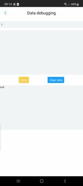
BTW, does anyone know if any sort of protocol level debugging is possible with this:
Screenshot_1718781254402.jpg
This is a "data debugging" part of the "smart plug Pro 05" "SmartESS" software. As I need some way to log the data before my open source solution is working I connected this temporarily.

It would be great if one could test protocol commands without disconnecting, hooking up a different device etc during development.

The top most field is numeric only and it is labelled "Communication addrrss" (exactly like this) and there is 1 there when it is opened.

The lower box is where any text can be entered and with nothing is entered it says "Please enter debugging instructions". I tried various things. Modbus commands in decimal with no spaces, with spaces etc, but I always get "null" as answer.

If anyone knows please share.


Also, as I understand it modbus is a simple binary protocol, why people talk about "PSET" commands etc in this context? I thought modbus uses numeric commands for example 03 is read, 05 is write and so on.
 
There might an additional step required in order to acquire the permission.

Are you able to configure any of the useful parameters on the SRNE inverter?

Here's what I'm doing using Python:

Code:
import minimalmodbus
instrument = minimalmodbus.Instrument('/dev/ttyUSB0', 1, mode='rtu', debug=False)

# send default binary password 11111111
value = instrument.write_register(0xe203, 0b11111111, 0, 6, False)

# change failsafe shutdown 30v->29.8v, normally a privileged op
# (note: voltage registers are all stored w.r.t 12V, so for a 24v system divide intended values by 2)
value = instrument.write_register(0xe005, 14.9, 1, 6, False)
 
What serial settings are you using? Crossover or straight cable. Devices came with rs232 female ends on comms cables. So called "Datalogger" plugs work with them, but I've been struggling to get 1 byte of data from them.

I tried with a raspberry pi I buit for the purpose (4 rs232 ports all tested at 2400 baud between it and a USB-rs232 belkin adapter on a windows laptop - as that's the speed I read these inverters use on their serial ports) using minimal modbus python, but I could've messed that up so I downloaded Modbus Poll, MPPT tracker from Voltronic and Watchpower on the windows laptop.

Neither talks to neither inverter. I'm pretty sure I have the correct device IDs, but the rest? I read somewhere they use 2400 baud, no parity, 8 bits, 1 stop bit and that's what I used I also tried a bunch of other settings (19200 baud for example). Not a single byte received.... I can understand the rpi rs232 adapter may be bad, but both it and a belkin rs232 adapter on windows? Much more likely is that I have bad serial settings .So I'm asking here.

I know my device addresses are 1 for the EASUN SMH-II-K and 5 for Y&H because I can see them in dessmonitor. Other info I can see is "protocol version" which is 2428 for the EASUN (Voltronic Axpert MKS II clone) and 6416 for the Y&H (probably Voltronic Kodak, not sure, all are SRNE).

No idea if this means anything to anyone. However if you have any other SRNE inverter (powmr maybe?) and you do get it working in watchpower, MPPT tracker or Modbus Poll, please share your serial setup.
 
I just read this and scratched my head.

MODBUS proprietary word salads with dongles?

Crazy.
Modbus is supposed to be a simple Standard Modicon lets everyone use.

Dongles, reminds me of the thing Square D used to use on the Symax line of PLCs to force you to use their stuff and software.
Schieder got rid of all that and corrected the software for the Symax legacy equipment to work without a com Dongles. ( when they bought square D and merged the Symax stuff into the modicon line)

I can remember making serial and parallel cables for Modbus.
cant remember much about them.

Someone should get a slap for making a mess of what should be simple communications protocols.
 
What serial settings are you using? Crossover or straight cable. Devices came with rs232 female ends on comms cables. So called "Datalogger" plugs work with them, but I've been struggling to get 1 byte of data from them.

I tried with a raspberry pi I buit for the purpose (4 rs232 ports all tested at 2400 baud between it and a USB-rs232 belkin adapter on a windows laptop - as that's the speed I read these inverters use on their serial ports) using minimal modbus python, but I could've messed that up so I downloaded Modbus Poll, MPPT tracker from Voltronic and Watchpower on the windows laptop.

Neither talks to neither inverter. I'm pretty sure I have the correct device IDs, but the rest? I read somewhere they use 2400 baud, no parity, 8 bits, 1 stop bit and that's what I used I also tried a bunch of other settings (19200 baud for example). Not a single byte received.... I can understand the rpi rs232 adapter may be bad, but both it and a belkin rs232 adapter on windows? Much more likely is that I have bad serial settings .So I'm asking here.

I know my device addresses are 1 for the EASUN SMH-II-K and 5 for Y&H because I can see them in dessmonitor. Other info I can see is "protocol version" which is 2428 for the EASUN (Voltronic Axpert MKS II clone) and 6416 for the Y&H (probably Voltronic Kodak, not sure, all are SRNE).

No idea if this means anything to anyone. However if you have any other SRNE inverter (powmr maybe?) and you do get it working in watchpower, MPPT tracker or Modbus Poll, please share your serial setup.
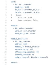
I know it's for esphome but if you take a look at this it might give you some answers the modbus info is under src/modules/inverter.
 
I know it's for esphome but if you take a look at this it might give you some answers the modbus info is under src/modules/inverter.
Thank you posting it.

I saw this resource and based on it I selected 2400 baud initially (see below)

Screenshot_20240627_074022_Chrome.jpg

I've had another look thinking maybe I missed something and there are few tiny things such as my python timeout is 50ms (I believe modbus poll uses 150ms), but watchtower and mppt tracked are 1s and the message still haven't came.

This is very weird. Perhaps I need to build that Esphome just to put this code on it and debug... I actually have the parts, but it'd probably be easier to rip an rj45 receptacle from some old non working device and making an extension cable with that to put an oscilloscope on the wire.

It is entirely possible there is a combination of things that makes it not work for me. For example it needs a crossover cable and it's 9600baud (I haven't tried it yet), but seeing that code again I suppose the speed is probably 2400 indeed. So what can it be? Different firmware? Ech... I expected lots of stuff, but such a simple task not working (to even get readings) is quite frustrating.

I just read this and scratched my head.

MODBUS proprietary word salads with dongles?
Well... Not that I want to defend since it's not working. But the protocol itself is pretty well documented. It's what you send through it (register numbers, passwords - thanks again @twrlp for posting that snippet), maybe serial settings as well as actual hw interface (crossover or not? I suppose yes because the "dongle" uses a male db9 connector which implements a sort of built-in crossover.
Someone should get a slap for making a mess of what should be simple communications protocols.
And not documenting it properly. One can wish, right?
 
An interesting development.... it appears possibly a crossover cable is needed.... From the PC I could get nothing back, but from a raspberry pi, once I increased timeout to 250ms (as in the code linked by @ThaiTaffy ) I did finally got a result!

So it is good progress. I'm also using a crossover adapter with two DB9 females (one of which is the uart to rs232 adapter which features an internal crossover) - so straight between female devices = crossover for male-female?

This is the only explanation I can think of why the windows PC is not working (I can't try crossover with it, because it has a male plug - I don't have a crossover adapter for that - I've ordered a bunch of both type db9 plugs so I can make my own cables.

Now, the code that worked for me is:
Code:
import minimalmodbus
instrument = minimalmodbus.Instrument('/dev/ttyAMA1', 5, mode='rtu', debug=True)
instrument.serial.baudrate = 2400
instrument.serial.timeout = 0.4
value=int(instrument.read_register(4534))
print("\n")
print(value)
print("\n")

And this is what I get as reply:
Code:
MinimalModbus debug mode. Create serial port /dev/ttyAMA1
MinimalModbus debug mode. Will write to instrument (expecting 7 bytes back): 05 03 11 B6 00 01 61 54 (8 bytes)
MinimalModbus debug mode. Clearing serial buffers for port /dev/ttyAMA1
MinimalModbus debug mode. No sleep required before write. Time since previous read: 25755787.82 ms, minimum silent period: 16.04 ms.
MinimalModbus debug mode. Response from instrument: 05 03 02 37 00 5F B4 (7 bytes), roundtrip time: 0.2 ms. Timeout for reading: 400.0 ms.


14080

When the register number is wrong this is how it looks like:
Code:
MinimalModbus debug mode. Create serial port /dev/ttyAMA1
MinimalModbus debug mode. Will write to instrument (expecting 7 bytes back): 05 03 02 16 00 01 65 F2 (8 bytes)
MinimalModbus debug mode. Clearing serial buffers for port /dev/ttyAMA1
MinimalModbus debug mode. No sleep required before write. Time since previous read: 25326591.45 ms, minimum silent period: 16.04 ms.
MinimalModbus debug mode. Response from instrument: 05 03 82 E1 50 (5 bytes), roundtrip time: 0.3 ms. Timeout for reading: 250.0 ms.

Traceback (most recent call last):
  File "/home/userone/dev/modbus/test2.py", line 5, in <module>
    value=int(instrument.read_register(534))
              ^^^^^^^^^^^^^^^^^^^^^^^^^^^^^
  File "/home/userone/dev/modbus/lib/python3.11/site-packages/minimalmodbus.py", line 484, in read_register
    returnvalue = self._generic_command(
                  ^^^^^^^^^^^^^^^^^^^^^^
  File "/home/userone/dev/modbus/lib/python3.11/site-packages/minimalmodbus.py", line 1283, in _generic_command
    return _parse_payload(
           ^^^^^^^^^^^^^^^
  File "/home/userone/dev/modbus/lib/python3.11/site-packages/minimalmodbus.py", line 1693, in _parse_payload
    _check_response_payload(
  File "/home/userone/dev/modbus/lib/python3.11/site-packages/minimalmodbus.py", line 3494, in _check_response_payload
    _check_response_bytecount(payload)
  File "/home/userone/dev/modbus/lib/python3.11/site-packages/minimalmodbus.py", line 3621, in _check_response_bytecount
    raise InvalidResponseError(errortext)
minimalmodbus.InvalidResponseError: Wrong given number of bytes in the response: 130, but counted is 0 as data payload length is 1. The data payload is: b'\x82'


I haven't tried writing the password in yet, as I'm trying to figure out the register for hybrid settings first (hopefully it exists).

Thank you for help in this thread.
 
Thank you posting it.

I saw this resource and based on it I selected 2400 baud initially (see below)

View attachment 224920

I've had another look thinking maybe I missed something and there are few tiny things such as my python timeout is 50ms (I believe modbus poll uses 150ms), but watchtower and mppt tracked are 1s and the message still haven't came.

This is very weird. Perhaps I need to build that Esphome just to put this code on it and debug... I actually have the parts, but it'd probably be easier to rip an rj45 receptacle from some old non working device and making an extension cable with that to put an oscilloscope on the wire.

It is entirely possible there is a combination of things that makes it not work for me. For example it needs a crossover cable and it's 9600baud (I haven't tried it yet), but seeing that code again I suppose the speed is probably 2400 indeed. So what can it be? Different firmware? Ech... I expected lots of stuff, but such a simple task not working (to even get readings) is quite frustrating.


Well... Not that I want to defend since it's not working. But the protocol itself is pretty well documented. It's what you send through it (register numbers, passwords - thanks again @twrlp for posting that snippet), maybe serial settings as well as actual hw interface (crossover or not? I suppose yes because the "dongle" uses a male db9 connector which implements a sort of built-in crossover.

And not documenting it properly. One can wish, right?
I'm away from home ATM so poking around my own code would be tiresome and possibly problematic but what I can tell you is I use a max3232m to convert from rs232 to uart I vaguely remember much of the hardware being described badly on the odya github tx/Rx being mixed for starters though with some minor changes I got it working(not after cooking a few max chips due to ground issues).

I also remember the modus poll having to be 150ms for some reason that escapes me now. On the cable side the odya github did have the correct terminations for the rj45, but the section on having every available register in order didn't apply to me.

I'm home in a few days I can debug the modbus/UART then and send you any data you need if you haven't fixed it by then.
That would be great :)

So far I'm trying to get sense of the data so having someone with working code to talk to would be great.

An example of this data I'm trying to make sense of is: I get register for AC grid voltage and I get 44809 (real voltage measure by another inverter is 250.9).

Edit: I believe we need to swap the bytes in the response. On the example of grid frequency I get 05 03 02 F5 01 CF 14 as a response which is F5 01, minimalmodbus interprets it as F501=62721 in decimal, while it should be 01F5=501 which makes a lot more sense if we're multiplying by 0.1 to get the real value.
 
Last edited:
Yes there's a ton of multiplying filters if I remember correctly just had a quick look at the code for voltage and it's somehow offset by current input but not clever enough to work out how.

lambda: |-
if (!id(grid_active).state) {
return 0.0;
}
return swapBytes(x);
filters:
- multiply: 0.1
- offset: ${inverter_voltage_offset}
- heartbeat: 10s
on_raw_value:
then:
- lambda: !lambda |-
if (!id(grid_active).state) {
id(pzem_grid_voltage).publish_state(0.0);
id(pzem_grid_current).publish_state(${pzem_current_offset} * -1);
id(pzem_grid_power).publish_state(0.0);
id(pzem_grid_power_factor).publish_state(0.0);
}

Pzem is a separate meter I'm using though I'd also have to check if that has multipliers also
Thanks. I figured out how to list stuff from documented registers. So far I haven't found a setting for grid export limit (is available through the panel). It is one that interests me most.

Regarding multipliers it is mostly 0.1 what I saw so far, but the byte order is swapper. Essentially every 16 bit value comes least significant then most significant. Then if I request a number of registers in one go I get crc error (no error for just one). So I suspect this reverse order affects crc calculation, but only for multiple value answers somehow?
 
And I found this on a Polish language forum which is very useful :) I now have a way to read grid tie current and status.

Code:
System setting
---------------
read system time
05 03 17 8E 00 06 A1 D3
Set system time: (2024-04-11 19:19:53)
05 10 17 8E 00 06 0C 07 E8 00 04 00 0B 00 13 00 13 00 35 15 AE


Read: Clear All Historical Power Generation
05 03 13 89 00 01 50 E0
Write:
05 06 13 89 00 01 9C E0


Grid setting
--------------
AC Input Range
05 03 13 9B 00 01 F0 E5
Set:
- appliance: 05 06 13 9B 00 00 FD 25
- UPS:  05 06 13 9B 00 01 3C E5


Battery setting
----------------
Charger Source Priority
05 03 13 99 00 01 51 25
Set:
- solar priority: 05 06 13 99 00 00 5C E5
- solar & utility: 05 06 13 99 00 01 9D 25
- solar only: 05 06 13 99 00 02 DD 24
 resp for solar only: 05 03 02 00 02 C8 45
 
Max Total Charge Current
05 03 13 9E 00 01 E0 E4
Set:
- 10A: 05 06 13 9E 00 0A 6D 23
- 30A: 05 06 13 9E 00 1E 6D 2C
- 160A: 05 06 13 9E 00 A0 ED 5C

Max Utility Charge Current
05 03 13 A0 00 01 81 28
Set:
 - 2A: 05 06 13 A0 00 02 0D 29
 - 20A: 05 06 13 A0 00 14 8C E7
 - 100A: 05 06 13 A0 00 64 8D 03

Battery Type
05 03 13 9C 00 01 41 24
Set:
 - AGM: 05 06 13 9C 00 00 4C E4
 - flooded: 05 06 13 9C 00 01 8D 24
 - user: 05 06 13 9C 00 02 CD 25
 - LIB:  05 06 13 9C 00 03 0C E5
 
Bulk Charging Voltage
25.0~31.5(24V) 48.0~61.0(48V)
05 03 13 A3 00 01 71 28
 Set 56.3V: 05 06 13 A3 02 33 3D 9D


Floating Charging Voltage
25.0~31.5(24V) 48.0~61.0(48V)
05 03 13 A4 00 01 C0 E9
 Set 54.6V: 05 06 13 A4 02 22 4C 50

Low Battery Cut-off Voltage
20.0~24.0(24V) 40.0~48.0(48V)
05 03 13 A5 00 01 91 29
 Set 42.0V: 05 06 13 A5 01 A4 9C C2

Comeback utility mode voltage point (SBU priority)
21.0~25.5(24V) 42.0~51.0(48V)
05 03 13 A1 00 01 D0 E8
 Set 43.0V: 05 06 13 A1 01 AE 5D 04

Comeback battery mode voltage point (SBU priority)
24.0~29.0(24V) 48.0~58.0(48V)
05 03 13 A2 00 01 20 E8
 Set 52.0V: 05 06 13 A2 02 08 2D 8E


Battery Equalization
05 03 13 93 00 01 71 27
 Set:
 - prohibited: 05 06 13 93 00 00 7C E7
 - enabled: 05 06 13 93 00 01 BD 27

Battery Equalization Voltage
25.0~31.5(24V) 48.0~61.0(48V)
05 03 13 A6 00 01 61 29
 set 58.0V:  05 06 13 A6 02 44 6D BA

Battery Equalized Time
5min~900min
05 03 13 A7 00 01 30 E9
 set 60min: 05 06 13 A7 00 3C 3D 38
 
Battery Equalized Timeout
5min~900min
05 03 13 A8 00 01 00 EA
 set 120min: 05 06 13 A8 00 78 0D 08

Battery Equalization Interval
0~90days
05 03 13 A9 00 01 51 2A
  set 30days: 05 06 13 A9 00 1E DC E2
 
Battery Equalization Activated Immediately
05 03 13 94 00 01 C0 E6
 set:
 - prohibited: 05 06 13 94 00 00 CD 26
 - enabled: 05 06 13 94 00 01 0C E6

Accumulator setting
Buzzer Alarm
05 03 13 8A 00 01 A0 E0
 set:
 - prohibited: 05 06 13 8A 00 00 AD 20
 - enabled: 05 06 13 8A 00 01 6C E0

Beeps While Primary Source Interrupt
05 03 13 8F 00 01 B0 E1
 set:
 - prohibited:  05 06 13 8F 00 00 BD 21
 - enabled: 05 06 13 8F 00 01 7C E1


LCD Backlight
05 03 13 8C 00 01 40 E1
 set:
  off: 05 06 13 8C 00 00 4D 21
  on: 05 06 13 8C 00 01 8C E1

Return To The Main LCD Page
05 03 13 90 00 01 81 27
  set:
   off: 05 06 13 90 00 00 8C E7
   on: 05 06 13 90 00 01 4D 27

Power Saving Mode
05 03 13 8B 00 01 F1 20
 set:
  - off: 05 06 13 8B 00 00 FC E0
  - on: 05 06 13 8B 00 01 3D 20
  resp for enabled: 05 03 02 00 01 88 44
 
Over Temperature Auto Restart
05 03 13 8E 00 01 E1 21
 set:
  off: 05 06 13 8E 00 00 EC E1
  on: 05 06 13 8E 00 01 2D 21

Record Fault Code
05 03 13 92 00 01 20 E7
 set:
   - off: 05 06 13 92 00 00 2D 27
   - on: 05 06 13 92 00 01 EC E7  

Restore Defaults
05 03 13 98 00 01 00 E5
 set:
  - off: 05 06 13 98 00 00 0D 25
  - on: 05 06 13 98 00 01 CC E5
 
Load setting
-------------
Output Source Priority
05 03 13 9A 00 01 A1 25
 set:
  - utility: 05 06 13 9A 00 00 AC E5
  - solar: 05 06 13 9A 00 01 6D 25
  - SBU: 05 06 13 9A 00 02 2D 24
  resp for mKs: 05 03 02 00 03 09 85
 
Output Voltage
05 03 13 9F 00 01 B1 24
 set 230V:  05 06 13 9F 00 E6 3D 6E
 

Output Frequency
05 03 13 9D 00 01 10 E4
 set:
  - 50hz: 05 06 13 9D 00 00 1D 24
  - 60hz: 05 06 13 9D 00 01 DC E4

Overload Auto Restart
05 03 13 8D 00 01 11 21
 set:
  - off: 05 06 13 8D 00 00 1C E1
  - on: 05 06 13 8D 00 01 DD 21

Transfer To Bypass Overload
05 03 13 8D 00 01 11 21
 set:
  - off: 05 06 13 91 00 00 DD 27
  - on: 05 06 13 91 00 01 1C E7

Other setting
-------------
GRID-tie operation
05 03 13 AA 00 01 A1 2A
 set:
  - off: 05 06 13 AA 00 00 AC EA
  - on:  05 06 13 AA 00 01 6D 2A
 resp for mKs?: 05 03 02 05 61 8B 3C

GRID-tie current
05 03 13 AB 00 01 F0 EA
 set:
  - 2A: 05 06 13 AB 00 01 3C EA
  - 4A: 05 06 13 AB 00 02 7C EB
  - 6A: 05 06 13 AB 00 03 BD 2B
  - 28A: 05 06 13 AB 00 0E 7C EE
  - 30A: 05 06 13 AB 00 0F BD 2E
 resp for mKs?: 05 03 02 00 00 49 84

Led pattern light
05 03 13 AC 00 01 41 2B
 set:
  - off: 05 06 13 AC 00 00 4C EB
  - on: 05 06 13 AC 00 01 8D 2B
  resp for mKs?: 05 03 02 00 0A C9 83
 
Dual output
05 03 13 AD 00 01 10 EB
 set:
  - off: 05 06 13 AD 00 00 1D 2B
  - on: 05 06 13 AD 00 01 DC EB
 
Enter the dual output functional vltage point
05 03 13 AE 00 01 E0 EB
 set:
  - 54.0V: 05 06 13 AE 02 1C ED 82

Unfortunately writing suceeds, but doesn't save... The device supposedly saves it, but then when I query again it has the old value.

I tried sending the password from @twrlp , but it results in error code 130 :-(

If anyone knows how t oimprove on this, it would be great.

just to clarify, I can change things like max charging current, but not grid tie current.... what I really would love to automate :-(
 
Last edited:
  • Like
Reactions: DPC
@ThaiTaffy have you managed to find a way to input a password to a POWMR via modnbus? I found an earlier response of yours indicating you haven't back then. Sadly I get wrong value response (error 130) when I try the password and register mentioned by @twrlp (
# send default binary password 11111111
value = instrument.write_register(0xe203, 0b11111111, 0, 6, False)
)

Here's what I'm doing using Python:

Code:
import minimalmodbus
instrument = minimalmodbus.Instrument('/dev/ttyUSB0', 1, mode='rtu', debug=False)

# send default binary password 11111111
value = instrument.write_register(0xe203, 0b11111111, 0, 6, False)

# change failsafe shutdown 30v->29.8v, normally a privileged op
# (note: voltage registers are all stored w.r.t 12V, so for a 24v system divide intended values by 2)
value = instrument.write_register(0xe005, 14.9, 1, 6, False)

Any chance you could say where did you get that register number? (and password value). Either one or the other is wrong for me, but maybe knowledge where you got it from will help me find the right values.
 
Last edited:
Any chance you could say where did you get that register number? (and password value). Either one or the other is wrong for me, but maybe knowledge where you got it from will help me find the right values.

Sure! The clearest I've found is from Midnite for their DIY series: https://www.midnitesolar.com/pdfs/Solar_inverter_charger_register_definition.pdf

I wonder if we are running the same firmware series. Can you try the following, and see if its output is similar to mine?

Python:
#!/usr/bin/env python3
import minimalmodbus
from time import sleep
from sys import exit

instrument = minimalmodbus.Instrument('/dev/ttyUSB0', 1, mode='rtu', debug=False)  # port name, slave address (in decimal)
instrument.serial.baudrate=9600
instrument.serial.timeout=1

for x in [ 0x000B , 0x0014 , 0x0015 , 0x0016 , 0x0017  ]:
    print("%x: %.2f" % (x, instrument.read_register(x, 0, 3, True)))

print("Build Date: %s ; S/N %s" % (instrument.read_string(0x021, 20, 3), instrument.read_string(0x035, 20, 3)))

My unit returns:

Code:
b: 4.00 # = inverter/charger
14: 517.00 # = SW v. 5.17-107
15: 107.00
16: 300.00 # HW v 3.00
17: 0.00 # ?
Build Date: Nov 12 2021 09:15:49 ; S/N SR-2112240001-300847
 
Sure! The clearest I've found is from Midnite for their DIY series: https://www.midnitesolar.com/pdfs/Solar_inverter_charger_register_definition.pdf
I see you've got actual documentation for the protocol... no such luck for my unit (nor any other in this price range at comparable power etc)
I was hoping you;ve used some clever trick I could replicate... not much hope then. I'll probably have to mess with the display/control board comms intercepting and injecting into that if I can't just randomly hit the register by trying.
I wonder if we are running the same firmware series.
I'm pretty sure we're not :-( based on the register numbers in the linked document being completely different. For example there are quite a few registers there in a block from 0x200, in my inverter these values are at decimal 45xx so completely different.
Can you try the following, and see if its output is similar to mine?

Python:
#!/usr/bin/env python3
import minimalmodbus
from time import sleep
from sys import exit

instrument = minimalmodbus.Instrument('/dev/ttyUSB0', 1, mode='rtu', debug=False)  # port name, slave address (in decimal)
instrument.serial.baudrate=9600
instrument.serial.timeout=1

for x in [ 0x000B , 0x0014 , 0x0015 , 0x0016 , 0x0017  ]:
    print("%x: %.2f" % (x, instrument.read_register(x, 0, 3, True)))

print("Build Date: %s ; S/N %s" % (instrument.read_string(0x021, 20, 3), instrument.read_string(0x035, 20, 3)))

My unit returns:

Code:
b: 4.00 # = inverter/charger
14: 517.00 # = SW v. 5.17-107
15: 107.00
16: 300.00 # HW v 3.00
17: 0.00 # ?
Build Date: Nov 12 2021 09:15:49 ; S/N SR-2112240001-300847
I'will tomorrow (I disconnected my raspberry pi for the night already) but I can say that if these registers return anything it will be quite a surprise because all the working register numbers I've found so far were in two blocks 4xxx and 5xxx.

I'll run it tomorrow.

I've spend all evening searching so I doub't there is any info online about the password register/value for my specirfic inverter type (POWMR/Y&H etc)

BTW, before you started using the password setting code, and you tried to set protected values did it behave the same as for me? It pretended to set, returned confirmation, but actually it didn't, or did it have some error message?
 
I see you've got actual documentation for the protocol... no such luck for my unit (nor any other in this price range at comparable power etc)
I was hoping you;ve used some clever trick I could replicate... not much hope then. I'll probably have to mess with the display/control board comms intercepting and injecting into that if I can't just randomly hit the register by trying.

I'm pretty sure we're not :-( based on the register numbers in the linked document being completely different. For example there are quite a few registers there in a block from 0x200, in my inverter these values are at decimal 45xx so completely different.

I'will tomorrow (I disconnected my raspberry pi for the night already) but I can say that if these registers return anything it will be quite a surprise because all the working register numbers I've found so far were in two blocks 4xxx and 5xxx.

I'll run it tomorrow.

I've spend all evening searching so I doub't there is any info online about the password register/value for my specirfic inverter type (POWMR/Y&H etc)

BTW, before you started using the password setting code, and you tried to set protected values did it behave the same as for me? It pretended to set, returned confirmation, but actually it didn't, or did it have some error message?
SRNE is the OEM for all of the units being discussed so the info from @twrlp 's link should be useful.

Nice thread, it's a bit over my head but I'm following along.
 
@ThaiTaffy have you managed to find a way to input a password to a POWMR via modnbus? I found an earlier response of yours indicating you haven't back then. Sadly I get wrong value response (error 130) when I try the password and register mentioned by @twrlp (
# send default binary password 11111111
value = instrument.write_register(0xe203, 0b11111111, 0, 6, False)
)


Any chance you could say where did you get that register number? (and password value). Either one or the other is wrong for me, but maybe knowledge where you got it from will help me find the right values.
No I'm out of country atm but hopefully heading back today but working out the lambda write isn't high on my priorities for now sorry. It's working out the hex code and how to implement it on initial boot up in my case as it seems this would likely be the most reliable way to get results.
 
SRNE is the OEM for all of the units being discussed so the info from @twrlp 's link should be useful.

Nice thread, it's a bit over my head but I'm following along.
So how does the register list from the link apply to this register map that is incomplete, but definitely correct? https://github.com/odya/esphome-powmr-hybrid-inverter/blob/main/docs/registers-map.md

I know there is more than one way to specify MODBUS register addresses. Sometimes a full address is given (what is sent on the wire). Sometimes one just gets "a function independent" register address one then has to add some offset to and +1 usually. I reviewed this list in hope maybe it can be matched, but it is not just numbers that differ. Order of the registers is different too.

So I suspect that SRNE may be making the boards, the cases etc, but these other "manufacturers" are putting it together and burning in their own firmware. I'm talking to a guy on another forum that has successfully reverse engineered such firmware (despite it being read protected with a 128 bit JTAG password). I was planning to use my 4.2KW inverter as a "bench testing unit" and have my go at reversing the firmware myself. But I was just told by all Aliexpress sellers the replacement I was expecting to be here in next few days will not even be in Europe before a month and half passes.... so I have no inverter I can dissemble and play with on the bench :-( I have to use it to power (parts of) the house (anyone doing off grid knows the perils of needing 25KW peak load capacity despite 200W base load, because once per year someone in the house may switch all the appliances on at the same time).

No I'm out of country atm but hopefully heading back today but working out the lambda write isn't high on my priorities for now sorry. It's working out the hex code and how to implement it on initial boot up in my case as it seems this would likely be the most reliable way to get results.
Sadly I don't know Home Assistant (yet - its on my list of things to do) so I can't comment at that at all. Regarding the hex codes for PZEM, if you have register numbers and what to write you can use python's minimalmodbus in debug mode to show you exact hex of what it sends on the wire. I'm not sure I understood the problem with the hex code you're resolving.

One more interesting bit of info. After all my messing with trying to write to the grid-in limit registers I went to switch it off manually and I noticed the display would not show the value. It would show the A symbol but no value.... Very curtious, because the query was showing I changed nothing. Evidently something did change. The display started displaying again after I set the value by hand. So something was changed. Perhaps a good sign? Sadly I have very little time to play with this when the sun i shining.
 
Last edited:

diy solar

diy solar
Back
Top