diy solar

diy solar

DC Voltage On EG4 18kpv Inverter AC Gird Connection During Power Outage

newmand45

New Member
Joined
Jun 25, 2024
Messages
5
Location
Texas
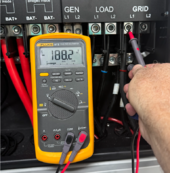
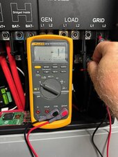
Installed is the EG4 18kpv inverter, two EG4 pro batteries and 10-400kw solar panels at home. There are B tap connectors in the service disconnect (conductors from the inverter to a 50 amp breaker in the panel or directly to the 200amp main breaker in the panel; controlled with interlock). During the utility inspection for parallel operation (no feed to the grid), the meter was pulled to simulate power outage with inverter, PV and batteries on. Utility used multimeter and measured zero AC voltage and between 190-198 DC voltage on the meter load lugs. Have worked with Signature Solar and two master electricians for 5 weeks reviewing as-built and conducting various tests. Two thoughts: Make G and N conductor changes (bonded only at the service disconnect) or inverter relay switch capacitors may not be working. Any thoughts?
 
Last edited:
Did EG4/SS provide a schematic with sufficient detail (around the relay area) to help root cause this? If so can you share it?

Is swapping the whole inverter an option? What pre-conditions did SS place on taking an exchange?
 
wpns and zanydroid, thanks for the input. It was suggested to try a 240v dc lamp base and incandescent bulb (hard to find) to check inverter. No schematic but after function testing and AC and DC v measurements, there is DC v on the AC side of the inverter. Working on the RMA.
 
Installed is the EG4 18kpv inverter, two EG4 pro batteries and 10-400kw solar panels at home. There are B tap connectors in the service disconnect (conductors from the inverter to a 50 amp breaker in the panel or directly to the 200amp main breaker in the panel; controlled with interlock). During the utility inspection for parallel operation (no feed to the grid), the meter was pulled to simulate power outage with inverter, PV and batteries on. Utility used multimeter and measured zero AC voltage and between 190-198 DC voltage on the meter load lugs. Have worked with Signature Solar and two master electricians for 5 weeks reviewing as-built and conducting various tests. Two thoughts: Made G and N conductor changes (bonded only at the service disconnect) or inverter relay switch capacitors may not be working. Any thoughts?
I'm having this same issue on my Luxpower 12k Unit. It happening on the grid port and the gen port, could you check and see if your gen port also has dc voltage on it. I.E. measure your gen port and see if you're seeing any dc voltage between Either L1 of the Gen Port and ground or L2 of the Gen and ground?
 
I wonder if a power supply that can accept 240V would be enough to test. There are many of those, and it would just have to derate by 50% in the rectifier stage.
 
I'm having this same issue on my Luxpower 12k Unit. It happening on the grid port and the gen port, could you check and see if your gen port also has dc voltage on it. I.E. measure your gen port and see if you're seeing any dc voltage between Either L1 of the Gen Port and ground or L2 of the Gen and ground?
The inverter installed is the EG4/Lux 18kpv. I did not measure voltages on the Gen Port, just the Grid Port (L1-N and L2-N) as I do not have a generator. After receipt of the new inverter, I will check the DC voltages and include the Gen Port.
 
Screenshot 2024-06-27 at 1.37.18 PM.png
Wow, color me surprised! Now I gotta find an appropriate load and see what the impedance of that signal is. I'm _guessing_ that's part of the grid impedance detection for the UL1741 or something, but that's just a guess.
 
View attachment 225043
Wow, color me surprised! Now I gotta find an appropriate load and see what the impedance of that signal is. I'm _guessing_ that's part of the grid impedance detection for the UL1741 or something, but that's just a guess.
More: Another inverter manufacturer (and 2 master electricians) find it odd that there is DC V on the AC side of the inverter and suspects the switch/capacitors may be dissipating that are connected between L1 to N and L2 to N to help reduce radio frequency interference as required by Federal Communication Commission regulations. Capacitors can take time some time and are in an "open circuit" condition (nothing connected providing a path for them to discharge) which is what could be present when a utility meter is removed.
 
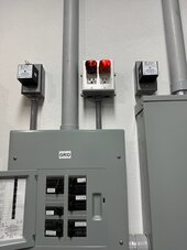
OK, so I connected a neon outlet tester to L1 (two neon bulbs plus current limiting resistors in parallel), and the voltage dropped to 90V (as expected), though it did light up the lights. Grid on the Left, glowing but not very brightly:
IMG_7110.jpeg
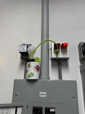
Then I plugged a 60W incandescent bulb into L2 and the Neon bulbs went out, and the voltage dropped to 25V on L1 (the neon tester), and 1V on L2 (the 60W bulb).
IMG_7111.jpegIMG_7112.jpegIMG_7113.jpeg

So I'm going to say that with an appropriate selection of incandescent "Pilot Lights" you can drive the DC "grid sensing voltage" as low as you want to make your Utility/AHJ/Electricians happy. I don't have my resistance substitution box or a selection of incandescent bulbs, but I can't imagine you need much load if a neon bulb can draw the voltage down to its breakdown voltage.

So there's nothing "wrong" with your inverter, all 18Kpv do that, and while the voltage is high, the impedance is really high too, and the hazard is nonexistent. No need for an RMA. @SignatureSolarJess

Signature Solar, your Utility, and your two Master Electricians should know this stuff or be able to figure it out without your having to spend 5 weeks and an RMA on it. I mean, it's their fracking job to know the difference between volts, amps, power, etc. Put a DVM on _any_ disconnected wire and measure the AC and DC potential.

Also, not to put too fine a point on it, but SS should be able to sort this out with one phone call to the EG4/LuxPower engineering team: "Hey, there's 190V (that Half Bus Voltage, Modbus VbusP?) DC on the Grid terminals to ground when there's no grid, what's with that?". "Oh, yeah, that's the grid detection circuit, very high impedance, if it bothers anyone put a 1W incandescent pilot light on each of L1 and L2."

/GrumpyOldMan
 
In off grid mode, the 18k opens up the grid relay but still monitors the grid for sync. I don't know if the DC voltage would still be on the grid connections, I never thought to test it.
 
In off grid mode, the 18k opens up the grid relay but still monitors the grid for sync. I don't know if the DC voltage would still be on the grid connections, I never thought to test it.
Even in Off-Grid mode the high impedance DC voltage is present. That's how mine is set up (off-grid mode but monitoring the grid) so I can thumb my nose at their power quality and still get notifications of grid outages that other folks are having. 8*)
 
OK, so I connected a neon outlet tester to L1 (two neon bulbs plus current limiting resistors in parallel), and the voltage dropped to 90V (as expected), though it did light up the lights. Grid on the Left, glowing but not very brightly:
View attachment 225171
Then I plugged a 60W incandescent bulb into L2 and the Neon bulbs went out, and the voltage dropped to 25V on L1 (the neon tester), and 1V on L2 (the 60W bulb).
View attachment 225172View attachment 225173View attachment 225174

So I'm going to say that with an appropriate selection of incandescent "Pilot Lights" you can drive the DC "grid sensing voltage" as low as you want to make your Utility/AHJ/Electricians happy. I don't have my resistance substitution box or a selection of incandescent bulbs, but I can't imagine you need much load if a neon bulb can draw the voltage down to its breakdown voltage.

So there's nothing "wrong" with your inverter, all 18Kpv do that, and while the voltage is high, the impedance is really high too, and the hazard is nonexistent. No need for an RMA. @SignatureSolarJess

Signature Solar, your Utility, and your two Master Electricians should know this stuff or be able to figure it out without your having to spend 5 weeks and an RMA on it. I mean, it's their fracking job to know the difference between volts, amps, power, etc. Put a DVM on _any_ disconnected wire and measure the AC and DC potential.

Also, not to put too fine a point on it, but SS should be able to sort this out with one phone call to the EG4/LuxPower engineering team: "Hey, there's 190V (that Half Bus Voltage, Modbus VbusP?) DC on the Grid terminals to ground when there's no grid, what's with that?". "Oh, yeah, that's the grid detection circuit, very high impedance, if it bothers anyone put a 1W incandescent pilot light on each of L1 and L2."

/GrumpyOldMan
Thanks for your help WPNS aka /GrumpyOldMan.
 
How does one prove to the inspectors the presence of high impedance DC voltage is not an issue? Will they really wait or understand a to connect a bulb/etc.
 
How does one prove to the inspectors the presence of high impedance DC voltage is not an issue? Will they really wait or understand a to connect a bulb/etc.
If you have inspectors that you think will care, you should hook up a couple of lightbulbs, and call them pilot lights, and the issue will not show up.
 
OK, so I connected a neon outlet tester to L1 (two neon bulbs plus current limiting resistors in parallel), and the voltage dropped to 90V (as expected), though it did light up the lights. Grid on the Left, glowing but not very brightly:
View attachment 225171
Then I plugged a 60W incandescent bulb into L2 and the Neon bulbs went out, and the voltage dropped to 25V on L1 (the neon tester), and 1V on L2 (the 60W bulb).
View attachment 225172View attachment 225173View attachment 225174

So I'm going to say that with an appropriate selection of incandescent "Pilot Lights" you can drive the DC "grid sensing voltage" as low as you want to make your Utility/AHJ/Electricians happy. I don't have my resistance substitution box or a selection of incandescent bulbs, but I can't imagine you need much load if a neon bulb can draw the voltage down to its breakdown voltage.

So there's nothing "wrong" with your inverter, all 18Kpv do that, and while the voltage is high, the impedance is really high too, and the hazard is nonexistent. No need for an RMA. @SignatureSolarJess

Signature Solar, your Utility, and your two Master Electricians should know this stuff or be able to figure it out without your having to spend 5 weeks and an RMA on it. I mean, it's their fracking job to know the difference between volts, amps, power, etc. Put a DVM on _any_ disconnected wire and measure the AC and DC potential.

Also, not to put too fine a point on it, but SS should be able to sort this out with one phone call to the EG4/LuxPower engineering team: "Hey, there's 190V (that Half Bus Voltage, Modbus VbusP?) DC on the Grid terminals to ground when there's no grid, what's with that?". "Oh, yeah, that's the grid detection circuit, very high impedance, if it bothers anyone put a 1W incandescent pilot light on each of L1 and L2."

/GrumpyOldMan
Could you check dc voltage between your Gen port and ground, make sure AC coupling is off, I want to see if it is doing the same as mine.
 

diy solar

diy solar
Back
Top