• Have you tried out dark mode?! Scroll to the bottom of any page to find a sun or moon icon to turn dark mode on or off!

diy solar

diy solar

EG4 18KPV Grid-Tied Wiring Question

dansolar

New Member
Joined
Mar 15, 2024
Messages
1
Location
North Carolina, USA
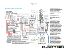
Hello! I have been researching installing a hybrid grid-tied solar power system with an EG4 18KPV Hybrid Inverter and (2) EG4 Wall batteries. In my research, I was reviewing the wiring diagrams provided by EG4 (specifically Diagram 4.4, "Whole Home Backup using a Feeder Tap", from the 18KPV manual). There were a few things that didn't quite make sense to me and I wanted to clarify why the instructions indicate this wiring.
  1. When connecting the 18KPV to the grid, the diagram shows no ground run between the feeder tap, the "PV Interactive System Fused Disconnect", and the 18KPV. Is this correct? I see how the 18KPV would still be grounded from the Feeder Tap > Feeder Tap Breaker > Manual Transfer Switch, but this appears to leave the "PV Interactive Disconnect" completely ungrounded.
  2. For the Manual Transfer Switch, on the "Only Utility" side, it appears that the Neutral wire bypasses the Transfer Switch and directly connects to the Main Breaker Panel. Is this to ensure that the Main Breaker Panel always has access to Neutral? (On that note, the diagram also shows a Ground connection between the Feeder Tap and the Transfer Switch in addition to the ground connection from the 18KPV and Feeder Tap Breaker, is this necessary?)
  3. Finally, what is the recommend method for "tapping" the ground wire in the Feeder Tap? EG4 recommends using Ilsco KUP-L taps for L1, L2, and Neutral, but it's unclear how Ground should be handled. (I'm also assuming these taps would take place in an electrical wiring trough between the Service Breaker and Feeder Tap Breaker / PV Fused Disconnect.)
Thanks for your help clarifying! I've been enjoying learning the "why's" behind these PV systems. :-)
EG4-18KPV-12LV-Manual-2.0.2_1.png
 
I am not certain on my answers.
1. There is no ground at the fused disconnect because neutral and ground are bonded at the main service breaker. The main breaker panel G and N are un-bonded and G will be combined in the transfer switch box with an auxiliary installed ground bus bar.

2. This confuses me also, and is how I found this post. According to the diagram the inverter neutral bus connects to the transfer switch and goes nowhere. But the inverter has a neutral bar which is also connected to the feeder tap and then the feeder tap is also connected to the neutral on the main breaker panel. I have no idea why there would be a neutral going into the transfer switch, I hope someone else on the forum can help answer. Because G+N can’t be bonded there in this diagram because they are bonded at the service breaker.

3. The main service breaker should have a ground+neutral bonding.(pic attached)
 

Attachments

  • IMG_0005.jpeg
    IMG_0005.jpeg
    177.4 KB · Views: 46
I had a conversation with EG4 regarding #2. The confirmed this is a diagram error. From the MTS neutral should also go-to the main breaker panel.
 
This is what I did in your situation (disclaimer: I'm not licensed but I tried to follow the NEC)
When connecting the 18KPV to the grid, the diagram shows no ground run between the feeder tap, the "PV Interactive System Fused Disconnect", and the 18KPV. Is this correct? I see how the 18KPV would still be grounded from the Feeder Tap > Feeder Tap Breaker > Manual Transfer Switch, but this appears to leave the "PV Interactive Disconnect" completely ungrounded.
I did ground ALL components. All components generally comes with a ground bar. Ground is only bonded to neutral at the first service breaker or panel. I've also installed an additional ground rod closer to the Inverter where the surge protectors are wired. This is to reduce the voltage that could be generated in the ground conductor itself in case of lightning. This new ground rod is also connected to the house ground which has two existing rods 20' away.

For the Manual Transfer Switch, on the "Only Utility" side, it appears that the Neutral wire bypasses the Transfer Switch and directly connects to the Main Breaker Panel. Is this to ensure that the Main Breaker Panel always has access to Neutral? (On that note, the diagram also shows a Ground connection between the Feeder Tap and the Transfer Switch in addition to the ground connection from the 18KPV and Feeder Tap Breaker, is this necessary?)
In my case, I've omitted the Feeder Tap Breaker, since the Main Breaker panel and the Main Service Breaker are less than 10' apart. The neutral effectively bypasses the 2-pole Manual Transfer switch (not part of the switching), but it's physically routed through it and connected to its un-bonded Neutral bar.

Finally, what is the recommend method for "tapping" the ground wire in the Feeder Tap? EG4 recommends using Ilsco KUP-L taps for L1, L2, and Neutral, but it's unclear how Ground should be handled
I've used these connectors to tap on L1,L2 (just personal preference), and ran the ground wire from the existing ground bar in the Main Service Breaker where I had a slot available. I have my taps located inside the Manual Transfer switch, but I would not recommend that if you can avoid it, as it may interfere with the mechanics of the manual transfer switch and an inspector could object it. It would be better to place it inside a wire channel as you suggested.

Hope it helps!
 
This is what I did in your situation (disclaimer: I'm not licensed but I tried to follow the NEC)

I did ground ALL components. All components generally comes with a ground bar. Ground is only bonded to neutral at the first service breaker or panel. I've also installed an additional ground rod closer to the Inverter where the surge protectors are wired. This is to reduce the voltage that could be generated in the ground conductor itself in case of lightning. This new ground rod is also connected to the house ground which has two existing rods 20' away.


In my case, I've omitted the Feeder Tap Breaker, since the Main Breaker panel and the Main Service Breaker are less than 10' apart. The neutral effectively bypasses the 2-pole Manual Transfer switch (not part of the switching), but it's physically routed through it and connected to its un-bonded Neutral bar.


I've used these connectors to tap on L1,L2 (just personal preference), and ran the ground wire from the existing ground bar in the Main Service Breaker where I had a slot available. I have my taps located inside the Manual Transfer switch, but I would not recommend that if you can avoid it, as it may interfere with the mechanics of the manual transfer switch and an inspector could object it. It would be better to place it inside a wire channel as you suggested.

Hope it helps!
confused though on what the transfer switch component is. The difference between this diagram and their line side one is this component. Do I still have to derate my panel if I do it this method? Looking to do full panel backup with grid tied
 
The transfer switch enables you to bypass the inverter and switch directly to grid power, allowing you to isolate the inverter for troubleshooting, removal, or maintenance.
 
The transfer switch enables you to bypass the inverter and switch directly to grid power, allowing you to isolate the inverter for troubleshooting, removal, or maintenance.
I guess the frustrating part is that there are no vendors that sell the kit to do this. To do the feeder taps in your plan, i need a main service breaker, wiring gutter, feeder tap possible feeder tab breaker, and a manual transfer switch. i realize there are many variations, but I haven't found a solar provider that outlines components to do this.
 
I have one panel as a "Grid" box, which gets it's input from the Meter, and feeds the parallel inverter inputs and a couple of other grid-only circuits.

I have a "House" box which has as input either "Grid" or the two inverters with an interlockkit.com breaker interlock so they can't both be on at the same time. Then the outputs to various sub-panels and other loads.

Switching the house from Inverters to Grid happens in the House box:
Switch off the "Inverter Output" breakers.
Move the Interlock bar.
Switch on the "Grid" breaker.
 
Something to keep in mind: My power company required me to replace the main switch that feeds the inverter (in our case, the 200A Main Service Breaker in the diagram) with a 200A lockable blade switch. I've used a GF224NR to comply. I was really frustrated because I couldn't get a technical explanation of why they won't accept a 200A breaker which I installed for this purpose. Before you install your own Main Service Breaker, make sure it complies with your local power company rules.
 
I have one panel as a "Grid" box, which gets it's input from the Meter, and feeds the parallel inverter inputs and a couple of other grid-only circuits.

I have a "House" box which has as input either "Grid" or the two inverters with an interlockkit.com breaker interlock so they can't both be on at the same time. Then the outputs to various sub-panels and other loads.

Switching the house from Inverters to Grid happens in the House box:
Switch off the "Inverter Output" breakers.
Move the Interlock bar.
Switch on the "Grid" breaker.
I'm waiting for my 18kpv to be delivered and working on wiring it up exactly this way. Could you take a look at this diagram and confirm this is what you're doing? What breakers did you end up getting for 200 amp branch breakers? My main panel is Siemens but open to anything for the grid box.

Thanks!
 

Attachments

  • WiringDiagram.png
    WiringDiagram.png
    200.3 KB · Views: 61
I'm waiting for my 18kpv to be delivered and working on wiring it up exactly this way. Could you take a look at this diagram and confirm this is what you're doing? What breakers did you end up getting for 200 amp branch breakers? My main panel is Siemens but open to anything for the grid box.

Thanks!
You've got it! Since my grid transformer's only good for 100A, and my peak recorded consumption is somewhere around 20KW (83-ish amps), I went with 100A breakers everywhere:
Screenshot 2024-09-14 at 8.38.26 AM.png

Screenshot 2024-09-14 at 8.38.47 AM.png


Screenshot 2024-09-14 at 8.39.10 AM.png
 

diy solar

diy solar
Back
Top