diy solar

diy solar

Supply side or Feeder tap? Inverter outage concerns? SolArk 15k / EG4 18KPV

PeteYates

New Member
Joined
Jun 27, 2023
Messages
29
Location
85253
Hi again, I am seeking some clarification on design / install configuration for a 14kw PV with hybrid inverter and 30kwh battery storage.

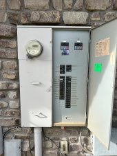
I have a Cutler hammer HP404040SH with max rating of 400amps (pic below). It has a 200A service breaker "A" with main breaker panel that provides service to half the home including 3 A/C units. The main panel also has a 200A service panel "B" breaker that feeds a separate breaker panel at the other end of the house which also has 3 A/C units attached. The branch circuit stab max at 225Amps.
I am looking to peak shave for the entire house (therefore whole house backup required) and seeking to reduce peak hour usage by 75% in hottest months (i.e. 10kwh down to 3kwh).
Based on the above, I do have a few questions:-
a) What installation configuration do I need? Supply side or feeder tap? What is the modification to the standard EG4 (fig 4.3) or Sol Ark install to accommodate the 2 branches?
b) How can I uprate the system to allow more than 40Amps to be backfed?
c) In a supply side or feeder tap, if the inverter fails (EG4 18kpv or SolArk 15k) will grid supply to the house be automatically shut down? I see the call for a manual transfer switch but that isn't useful if you are not home.
d) My peak hourly load is over 20kw (so this is not instantaneous peak), is there any danger in overloading the inverter with grid pass through?

Any other look outs in what I am doing?

Thanks in advance


IMG_1195(1)mainpanel.jpg
 
Supply side or feeder tap?

A easy way to cut your flapping around the design space is to call up your AHJ or POCO and ask about line side vs load side. (if that's what you mean). Hopefully (by my preference) they tell you line side requires so much red tape you don't have to worry about it anymore.

I am looking to peak shave for the entire house (therefore whole house backup required) and seeking to reduce peak hour usage by 75% in hottest months (i.e. 10kwh down to 3kwh).

(Control theory)
For peak shaving the main consideration is whether you can put the CTs in the correct position to detect the major loads, so that the inverter can know to offset those. Simple analysis would say, if you can put CTs in the line feeding the 400A bus, then you can offset everything. But if your major loads are on one of the 200A, or you can refactor accordingly, then you can put the CTs on the load side of the 200A breakers. Where CTs are convenient to install, cannot be answered with just your text and the rating sticker. Need photos of the wiring compartment(s) with the dead front off.

(Power engineering)
As for where the hybrids connect in electrically speaking, this is more a question around where your critical loads are, ease of installation, and future proofing. And some of these are somewhat lumpy tradeoffs with no clear local or global optima that is applicable to all situations.

b) How can I uprate the system to allow more than 40Amps to be backfed?

I think you parallel multiple of them into the interconnection point, there should be wiring diagrams in both manuals. As long as the interconnection has 200A OCPD nothing exotic needs to be done apart from making sure the splicing is done with equal enough feeder resistance on each path.

Put another way, compared to a XW+ or SolArk 12K which do not have (IIRC) 200A internal transfer rating the 18kpv and 15k are a lot simpler. You get what you pay for, in a good way.

c) In a supply side or feeder tap, if the inverter fails (EG4 18kpv or SolArk 15k) will grid supply to the house be automatically shut down? I see the call for a manual transfer switch but that isn't useful if you are not home.
I think it depends on what kind of failure it is, as to whether the hybrid would be able to flip its transfer relay. And whether the transfer relay requires continuous power / continuously alive control board to do.

I think if this is important you need a detection & escalation runbook, IE calling a neighbor or whatever. I'm not sure adding an external control system to throw an automatic transfer relay will add the necessary robustness. Maybe it will ?


d) My peak hourly load is over 20kw (so this is not instantaneous peak), is there any danger in overloading the inverter with grid pass through?
It's within the 200A transfer rating on the spec sheet (IIRC for those two inverters), so up to you whether you trust the spec sheet to have enough headroom.
 
A easy way to cut your flapping around the design space is to call up your AHJ or POCO and ask about line side vs load side. (if that's what you mean). Hopefully (by my preference) they tell you line side requires so much red tape you don't have to worry about it anymore.
There are already 2 x 200A breakers installed so a line side tap shouldn't be necessary. Intercept the wires between the 200A breaker and the panel. Feed the Inverter input then supply the panel from the inverter output. Unless I'm missing something?
(Control theory)
For peak shaving the main consideration is whether you can put the CTs in the correct position to detect the major loads, so that the inverter can know to offset those. Simple analysis would say, if you can put CTs in the line feeding the 400A bus, then you can offset everything. But if your major loads are on one of the 200A, or you can refactor accordingly, then you can put the CTs on the load side of the 200A breakers. Where CTs are convenient to install, cannot be answered with just your text and the rating sticker. Need photos of the wiring compartment(s) with the dead front off.
The CT's are primarily for controlling Sell Back. If the inverter is in front of the main panel there is nothing else upstream as would be the case if the inverter were feeding a subpanel and excess solar was being pushed upstream to a main panel. You would want to consume 100% of PV production in the main leaving nothing to back-feed the grid..
I think you parallel multiple of them into the interconnection point, there should be wiring diagrams in both manuals. As long as the interconnection has 200A OCPD nothing exotic needs to be done apart from making sure the splicing is done with equal enough feeder resistance on each path.
In this particular case 2 inverters, 1 for each panel would be ideal.I think it depends on what kind of failure it is, as to whether the hybrid would be able to flip its transfer relay. And whether the transfer relay requires continuous power / continuously alive control board to do.

Lastly, the manual transfer switch mentioned, I believe is there as a Maintenance Bypass. The transfer switch is built into the inverter.
 
There are already 2 x 200A breakers installed so a line side tap shouldn't be necessary. Intercept the wires between the 200A breaker and the panel. Feed the Inverter input then supply the panel from the inverter output. Unless I'm missing something?
This is what I believe would be better off-hand to avoid the POCO/AHJ challenges as well as overcoming the fact that the hybrids are 200A rated. If you're going to not take advantage of the EZ mode installs 200A capability gives you, might as well go with cheaper inverters /s (only sort of). (1)

The CT's are primarily for controlling Sell Back. If the inverter is in front of the main panel there is nothing else upstream as would be the case if the inverter were feeding a subpanel and excess solar was being pushed upstream to a main panel. You would want to consume 100% of PV production in the main leaving nothing to back-feed the grid..
CT does not need to be worried about so much if the inverter is in front of the 200A panel with majority of loads.

If the inverter ends up being fed a different way (IE via a 50A branch breaker, see point (1) above for why this feels silly), or the major loads are on the other 200A panel (might make sense if you want to automatically turn them off in an outage) then CT placement needs to be considered.

Note there is another theoretical way to solve the problem of not being able to wedge the CT into the 400A side. Namely paralleling (?) two sets of CTs, one on each 200A, and with matching polarity. CTs can add in the electrical domain with this one simple trick :laugh:

In this particular case 2 inverters, 1 for each panel would be ideal.I think it depends on what kind of failure it is,
This might cause some awkwardness with either parallel stacking the two inverters together and/or sell back control.

For sell back control side, suppose all loads are on one inverter but all current solar is coming in on the other one. Oops.

For stacking, if the implementation heavily assumes that there is either passive current sharing, or uses a current sharing signal between the inverters, having the inverters see different load is not going to make the inverter engineers happy.

Lastly, the manual transfer switch mentioned, I believe is there as a Maintenance Bypass. The transfer switch is built into the inverter.
Yes that is consistent with what I was saying. OP seemed to want to think through some edge case failure mode. I think the best practice of vocal folks on this forum is to have maintenance bypass.
 
Thanks Gents,

To add some additional detail.
When I say peak shaving, I mean I am looking to reduce the grid consumption during peak hours by supplying partially from the 30kwh battery bank (discharge up to about 8kw in all of the peak hours which equates to a 80% reduction in peak usage from grid).
The demand at peak is predominantly driven by the 6 Air conditioning systems with 3 units off panel A and 3 off panel B. I have the units on pre cool routines so have minimized their run times during peak and know the consumption patterns. So the loads are on both panels and I need to supply from the battery rack to each panel as though it were 1 panel in order to off set total usage.

I am considering only 1 inverter (EG4 18KPV or solark 15k), 1 battery rack (30kwh) and 14kw solar panel array at this stage. I am limited on solar space.

The ROI on this project is predominantly around reduction of peak hour consumption, followed by partial elimination in off peak consumption. While there will be sell back, it will be minimal.

The EG manual has some standard install diagram including supply side tap and feeder tap (both configs are downstream of the utility meter).


The failure modes I am asking about are relative to being away from home. If power fails and trips the inverter (and doesn't reset on restoration) or if the inverter fails and disconnects the grid, and I am away, then the consequences could be costly (excessive heat build up in AZ, fridge spoils, no security etc etc). If there was notification capability then I could possibly do a manual workaround but I believe with power out there would be no notification. Ideally, the default inverter failure or trip would be to switch to main grid supply. In the absence of this, I may be forced to manually switch to grid when I am away...not ideal.


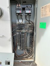
Below are pics of the entire panel and the breaker side opened up. mainpanelopenfullvw.jpg
The AHJ don't provide any advice here. It's more of a game of decide your design and then they poke holes in it until you align.

mianpanelopenview.jpg
 
Last edited:
When I say peak shaving, I mean I am looking to reduce the grid consumption during peak hours by supplying partially from the 30kwh battery bank (discharge up to about 8kw in all of the peak hours which equates to a 80% reduction in peak usage from grid).
The demand at peak is predominantly driven by the 6 Air conditioning systems with 3 units off panel A and 3 off panel B. I have the units on pre cool routines so have minimized their run times during peak and know the consumption patterns. So the loads are on both panels and I need to supply from the battery rack to each panel as though it were 1 panel in order to off set total usage.

OK understood. Would the AC units be able to fit on one panel and be OK load calculation wise? The reason I'm thinking this is helpful is in case you cannot find answers from EG4 or SolArk on having an energy meter or CT that is capable of handling the potential of 320-400A of primary current without going out of spec, in which case the extreme conservative approach would be to only put CTs after a single 200A breaker.

Based on your picture with deadfront off, it is very easy to add CTs in there all three locations (before the 2x200A, or after it). The question would be whether the inverters have a supported configuration for potential readings over 200A. IE will it fry if the secondary current gets too high or just clamp the reading at 200A (clamping will be electrically safe, it'll just stop shaving at 200A and leave anything above 200A consuming from grid. Actually just realized you need 4 inverters to shave 200A anyway, hahaha). There should definitely be easy ways for the manufacturer to implement this for either CT or energy meter based approaches, however the devil is in whether they do this & how you can find out. Maybe you can tag the EG4 technical rep on this forum to see what the recommended configs are for >200A. If you do that on the 18kpv megathread probably some user will have ideas.

The failure modes I am asking about are relative to being away from home. If power fails and trips the inverter (and doesn't reset on restoration) or if the inverter fails and disconnects the grid, and I am away, then the consequences could be costly (excessive heat build up in AZ, fridge spoils, no security etc etc). If there was notification capability then I could possibly do a manual workaround but I believe with power out there would be no notification. Ideally, the default inverter failure or trip would be to switch to main grid supply. In the absence of this, I may be forced to manually switch to grid when I am away...not ideal.

Hmm, off hand what I can think of for backup notifications is a home security system with battery backup, cellular modem, and monitoring subscription. You can probably then add a custom zone with a special kind of sensor with inputs for arbitrary binary analog signals. I think they're called dry contact sensors. Then you can get the same quality of notification as direct automatic dispatch to fire or police; FWIW the dispatch pipeline is certified to some UL spec. Ideally you would be able to config the security system to dispatch this zone to you instead of emergency services, since that would be an inappropriate call (and in my city that would be a $$ charge per visit).

The hardware is all very affordable, however the monitoring plan is probably $15/month (including the cell subscription).

The backup batteries on the one I use are NiMh, by default have 4 hours of durability and can be extended to 24 hours. The modem is upgradable as cell technologies are deprecated. 4 hours is plenty since you'll never need more than like 5 min of power to notify yourself.

There may be cheaper high availability telemetry sort of things out there, I'm sure there's a good forum or subreddit. Maybe even home security forums will have people familiar with more direct ways of monitoring.

You can ask the inverter manufacturer(s) what the default failure should be, it's probably fail-to-bypass assuming it doesn't blow its brains out during the failure.
 
Feedback to the forum. This is the Sol Ark response (less than 24 hours after emailing them. Not heard from SS yet nor from utility company


Thank you for reaching out to us.

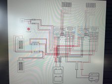
If you are wanting whole home backup on a 400A service, you need two 15K inverters to accommodate 400A of pass-through, as each 15K has 200A pass-through from grid to load. If you only wish to backup one of your two load panels, then a single 15K would suffice.

A single 15K will output a maximum of 15kW. When on battery power only, this output decreases as the battery voltage decreases, more likely to be in the range of 13.5kW to 14.5kW.

With a peak load of 20kW, it would not overload a single inverter if the grid is available. If the grid is down, it would overload a single inverter.

If the inverter does overload and fault, it will reset and attempt to power loads again. If it trips 5 consecutive times, the inverter will require a manual power cycle. The 15K will still allow grid pass-through in a faulted state, as long as the grid is up.
solark400A.jpg
 
That is a solid response from them and consistent with what I’ve had as a mental model. Main thing I overlooked in previous posts is the potential overload when off grid and you are away from home.

Also the desired power out behavior wasn’t clearly defined. If you want all loads to be powered with no risk of overload (IE more availability than grid since you are covering the grid downtime) you need to pay for some combo of two inverters (to hit your peak load) automatic load shedding like smart panel or relays, moving all critical loads to one subpanel, moving shed loads to relay controlled port on the inverter
 
Back
Top