diy solar

diy solar

Supply side tap

lapsmith

New Member
Joined
Apr 10, 2022
Messages
234
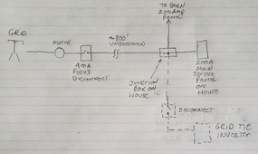
I'd like to use what may be considered a line side tap installation for my grid tie inverter to avoid having to de-rate my main service panel breaker.

1703530042823.png

I have two questions.

1. Since there is a disconnect between the meter and where I would connect the grid tie inverter, is this still considered a line side tap?

2. The wires from the junction box to the disconnect for the inverter will be sized for the inverter output at 48 amps so #6 gauge. This distance is about 3 feet. However, those #6 wires would only be protected by a 400 amp fused disconnect so it doesn't seem right or safe. OTOH, the same situation exists with the main service panel which is 200 amps. The wire going from the junction box to the main panel is 2/0, whereas the wire feeding the junction box is 350. So it seems either the original installer messed up, or I am missing something.
 
If the conductors for the taps are protected within 10' of the tap. Then the conductors can be sized by this protection device.
As long as the tap conductors are no smaller than 10% of the feeding conductors.

To clarify the last part.
With a 400a feeder. All taps must be a minimum of 40a.
 
That's great news...although a bit surprising. If I understand correctly then, I in my case, I can connect a #6 wire to the multitap connector* inside the junction box which is protected by a 400 amp fuse PROVIDED:
  • That the #6 wire run is less than 10 feet
  • There is a protection device within that distance
  • The protection device is 40 amps or greater. (In my case it will be 60 amps for the 48 amp inverter)
*The multitap already has 350 and 2/0 wires connected to it, but there is a spare port

Wow, I don't know how I ever would have found that information, even after hours of searching. Thanks a bunch!
Yup
You have got it.
 
The #6 wire run will have to be protected to the standards required by a tap. It depends on location. Inside a structure some standard of conduit, I think EMT is fine but maybe weaker is OK.

705.12(B) calculations need to be done to check tap ampacity limits from having two power sources. If you put the #6 at the opposite end of the taps from your existing taps you are probably OK.
 
If you are considering to backfeed from the other panels later on these 705.12B calculations will get more complicated. It is better to have your tap to go to a new combiner subpanel if you plan to expand in the future. Everything is simpler.

You can easily scale this subpanel to pretty high ampacity without much cost, since it’s only a 10 ft run. Could have a cost neutral step up in ampacity by using Al feeder

You can use a main breaker on this subpanel as the disconnect/OCPD for the tap
 
The #6 wire run will have to be protected to the standards required by a tap. It depends on location. Inside a structure some standard of conduit, I think EMT is fine but maybe weaker is OK.
It will be inside a structure (on the opposite side of an outside wall) and I was planning on using rigid metallic conduit.
705.12(B) calculations need to be done to check tap ampacity limits from having two power sources. If you put the #6 at the opposite end of the taps from your existing taps you are probably OK.
Good point, thanks and will do.
 
If you are considering to backfeed from the other panels later on these 705.12B calculations will get more complicated. It is better to have your tap to go to a new combiner subpanel if you plan to expand in the future. Everything is simpler.

You can easily scale this subpanel to pretty high ampacity without much cost, since it’s only a 10 ft run. Could have a cost neutral step up in ampacity by using Al feeder

You can use a main breaker on this subpanel as the disconnect/OCPD for the tap

No plans to expand later as I am out of space for more solar panels. I have 40 360W panels.

BTW, if anyone is in the Houston area, my local solar distributor is selling these panels at a great price of $70 each.
 
It will be inside a structure (on the opposite side of an outside wall) and I was planning on using rigid metallic conduit.
OK, I would suggest thinking about upsizing the conduit, there are a couple of plausible future reconfigurations. Like adding more grid tie or reconfiguring it to a hybrid.

If it's hypothetically reconfigured to a hybrid to feed the house panel then you need to pull 6 feeder conductors through. 2x L/L/N, one for AC in for hybrid and one for AC out. And that would require derating using the 4-6 CCC column.

OTOH if it's easy enough to rip/reconfigure in the future then no need to worry about this.
 
Any reason why you have your panel 300ft past your meter?

That 300f and all it’s losses you’re paying for as the meter picks it up.

My panel is about 6’ from the meter set.
 
OK, I would suggest thinking about upsizing the conduit, there are a couple of plausible future reconfigurations. Like adding more grid tie or reconfiguring it to a hybrid.

If it's hypothetically reconfigured to a hybrid to feed the house panel then you need to pull 6 feeder conductors through. 2x L/L/N, one for AC in for hybrid and one for AC out. And that would require derating using the 4-6 CCC column.

OTOH if it's easy enough to rip/reconfigure in the future then no need to worry about this.
I ordered a Growatt 11.4KW inverter which is already a hybrid. It can handle something like 22KW of panels, but I don't have room for more and probably don't need. If I did, I could add more in series so no no worries about PV wire to the house (I ran enough for 4 strings). Also, the inverter will be right next to the house panel and I will also be adding a manual transfer switch and critical loads panel, but they will all be within a few feet of each other so any potential upgrades should be easy compared to this installation. Anyway, I appreciate the suggestion and I hope I'm not forgetting something! All these regulations keep sneaking up.
 
I ordered a Growatt 11.4KW inverter which is already a hybrid. It can handle something like 22KW of panels, but I don't have room for more and probably don't need. If I did, I could add more in series so no no worries about PV wire to the house (I ran enough for 4 strings). Also, the inverter will be right next to the house panel and I will also be adding a manual transfer switch and critical loads panel, but they will all be within a few feet of each other so any potential upgrades should be easy compared to this installation. Anyway, I appreciate the suggestion and I hope I'm not forgetting something! All these regulations keep sneaking up.

What accessories does it need to grid form? Does it need the second box with autotransformer and transfer relay?

I don’t think a manual transfer switch would be needed for a hybrid, except to bypass faulty equipment. Since I would expect the CLP to be fed from grid power via the hybrid.

You also need to upsize the conduit to accommodate putting a CT in the right place on your feeder to do self consumption. And there needs to be enough space in the splice location to accommodate one. Probably line side of your multiport so that the CT can observe the load from both subpanels. I’m not actually sure you can easily exclude the barn if reusing the existing multiport here.
 
Any reason why you have your panel 300ft past your meter?

That 300f and all it’s losses you’re paying for as the meter picks it up.

My panel is about 6’ from the meter set.
Good question. Short answer - I bought the house that way.
There is a POCO transformer on my property which is about 100 feet from the pole near the street. The house is another 300 feet from there. My guess is that the POCO would only run their wires a certain distance. Fortunately the builder/electrician ran 350 wire from the 400 amp disconnect to the house. At the house, it tees off and goes to the barn another 75 feet away. Both buildings have 200 amp service.
 
What accessories does it need to grid form? Does it need the second box with autotransformer and transfer relay?
Not sure I understand the question. It doesn't need any accessories that I know of after reading the manual. There is no mention of an autotransformer or transfer relay.
I don’t think a manual transfer switch would be needed for a hybrid, except to bypass faulty equipment. Since I would expect the CLP to be fed from grid power via the hybrid.
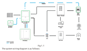
As a hybrid, I wouldn't have thought it need a transfer switch either, but the manual shows one:
1703604254435.png

And it will be nice to have a transfer switch for the following reasons. I will have a backup battery, but if the grid goes down, I don't necessarily want all the critical loads to come on automatically so I will use a manual transfer switch and then I can manage the critical loads. Another reason is that my backup battery will only be 10kwh. After a day or so without sunshine it will depleted. At that point I will tap into the 75kwh battery in my Tesla. Tesla does not condone this, but with the help of others on the Tesla forum, I figured out how to get about 1000 watts from the battery, so it would at least keep the fridge and lights on for days. When I tap into the Tesla, I need to isolate the inverter since I don't know if it would be happy being backfed through the critical loads circuit.
You also need to upsize the conduit to accommodate putting a CT in the right place on your feeder to do self consumption. And there needs to be enough space in the splice location to accommodate one. Probably line side of your multiport so that the CT can observe the load from both subpanels. I’m not actually sure you can easily exclude the barn if reusing the existing multiport here.
The Growatt doesn't need CT's to operate, from what I understand. It is an optional accessory that only provides data to the app. I may get one eventually, but I'd probably have to run separate conduit for that. But you bring up good points that I haven't thought of. I would probably install the CT's on the line side of my multitap, as you suggest. But since they may not fit on the 350 wire, what would happen if I installed them on the 2/0 going to the house? I'm guessing I would just get inaccurate data?
 
I don't think it is really called a line-side tap when it comes after the first OCP.

My old place was already set up that way, a 200A main breaker and meter in one box. New place I'm upgrading to 200A and doing the same (200A main breaker only panel, fed by a meter box.)

I don't feel at all bad about smaller gauge wires protected by OCP at the far end, so long as the wires are as large as required ground wire for the upstream protection. If there is a moderate overload, so wire heats up for a while until it clears, that will be through the downstream OCP. If there is a dead short in between which fast strips upstream OCP, required ground wire is of sufficient size.

For my 200A, that would be 6 awg copper. Yours is 400A (fast trip above 2000A, or whatever your fuse curve), so 3 awg:


From what Tim says, "40A" is considered sufficient. I guess that means 8 awg, since 10 awg has 40A ampacity but is only allowed 30A. Since it is inside conduit, other things are protected, but would rather avoid insulation damage.
But I might want to second-guess the code and go larger. In my case, couple of 100A branches will be 2 awg (plenty large), and 8 awg ground is considered sufficient but maybe I'll follow my reasoning and use 6 awg for ground.

I think main problem would be poor contact to conduit, which would be more resistive than copper and could have poor contact in places. If series resistance dropped current below 2000A, then it would flow a while. Again, fuses have their own characteristics different from breakers.


BTW, if anyone is in the Houston area, my local solar distributor is selling these panels at a great price of $70 each.

Please do, $0.19/W is a great price. Bunch of us bought from Inxeption for that price delivered, but that deal is sold out.

Also, the inverter will be right next to the house panel and I will also be adding a manual transfer switch and critical loads panel, but they will all be within a few feet of each other so any potential upgrades should be easy compared to this installation.

Interlocked backfed "generator" breaker in the house panel would let you manually supply any load from inverter.
Another one in critical loads panel would let you bypass inverter if it is down. Of course you'll also have OCP/disconnect before the inverter. Transfer switches are more expensive and often larger, but just a fused safety switch should work here.


Not sure I understand the question. It doesn't need any accessories that I know of after reading the manual. There is no mention of an autotransformer or transfer relay.

Some brands/models are 240V only, and some don't have relay separating grid input from output. If yours is 120/240V it probably contains everything.

And it will be nice to have a transfer switch for the following reasons. I will have a backup battery, but if the grid goes down, I don't necessarily want all the critical loads to come on automatically so I will use a manual transfer switch and then I can manage the critical loads. Another reason is that my backup battery will only be 10kwh. After a day or so without sunshine it will depleted.

You might want automatic backup of critical loads, like communications and alarm. Of course those may have 12V supply, could run off a battery, charger, PV panel.


The Growatt doesn't need CT's to operate, from what I understand. It is an optional accessory that only provides data to the app. I may get one eventually, but I'd probably have to run separate conduit for that. But you bring up good points that I haven't thought of. I would probably install the CT's on the line side of my multitap, as you suggest. But since they may not fit on the 350 wire, what would happen if I installed them on the 2/0 going to the house? I'm guessing I would just get inaccurate data?

Will you have a net-metering plan?
Without that, you could only feed downstream loads (protected loads panel).
But if you install CT just before junction box, then inverter can backfeed to house and barn, without backfeeding grid.
If you have net metering, no need because you can backfeed both house and grid freely.
If the plan gives less than 100% credit, you might want to measure backfeed and enable loads to use surplus (for full value rather than reduced credit.) Maybe with other meter/control not related to inverter.
If you have time of use, CT could tell inverter to charge battery rather than exporting during low rate times, discharge battery rather than importing at high rates. Assuming it implements such functions.
 
As a hybrid, I wouldn't have thought it need a transfer switch either, but the manual shows one:
I guess what hybrid means isn’t super standardized.


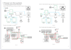
Look on page 3

1703608680417.png

I can tell SYN200-XH-US is a MID with ATS and autotransformer in it because it takes 240 from grid and inverter and outputs 120/240. Looks like the inverter does not have a CLP output

This inverter / battery type is proprietary and a little expensive to scale up battery storage on. Which isn’t my favorite situation. Not sure what options you have if that inverter is discontinued and you want to keep using the ARO

You need CTs in the appropriate place to detect the power to zero out. I don’t think CT on the home feeder is likely to work because at that point it will see the sum of inverter and grid. On the 400A side of the splice the CT may not fit / have chance of being subjected to too much current
 
I don't think it is really called a line-side tap when it comes after the first OCP.
That would be great. I emails my power company, but it usually takes days for a reply.
From what Tim says, "40A" is considered sufficient. I guess that means 8 awg, since 10 awg has 40A ampacity but is only allowed 30A. Since it is inside conduit, other things are protected, but would rather avoid insulation damage.
But I might want to second-guess the code and go larger. In my case, couple of 100A branches will be 2 awg (plenty large), and 8 awg ground is considered sufficient but maybe I'll follow my reasoning and use 6 awg for ground.

I think main problem would be poor contact to conduit, which would be more resistive than copper and could have poor contact in places. If series resistance dropped current below 2000A, then it would flow a while. Again, fuses have their own characteristics different from breakers.
I would consider 8 awg, but the multitaps that I found on line typically have a wire range of 350 to #6. Any smaller and I guess the screw doesn't make good contact with the wire. I don't know the exact multitap I have, but I'm guess it is similar.
Please do, $0.19/W is a great price. Bunch of us bought from Inxeption for that price delivered, but that deal is sold out.
Greentech Renewables is the company I bought from. The guy's name is Z (short for Zeniff) his email is zeniff.rodriguez@greentechrenewables.com. They are in Katy, TX and I don't know if they ship. I believe all they have left is panels.
Interlocked backfed "generator" breaker in the house panel would let you manually supply any load from inverter.
Another one in critical loads panel would let you bypass inverter if it is down. Of course you'll also have OCP/disconnect before the inverter. Transfer switches are more expensive and often larger, but just a fused safety switch should work here.
Hmm, I do have a generator breaker. Although it is not interlocked so I will have to fix that. It came that way when I bought the house. But how would I connect the inverter to the generator breaker? There is an outlet outside for the generator to plug into that runs to the breaker. Would you just make a cable to plug into that when needed?
Some brands/models are 240V only, and some don't have relay separating grid input from output. If yours is 120/240V it probably contains everything.
Oh, got it. The Growatt inverter (MIN11400TX-XH-US) is approved by my POCO and so it does separate from the grid.
You might want automatic backup of critical loads, like communications and alarm. Of course those may have 12V supply, could run off a battery, charger, PV panel.
True, those would be good loads to have automatic backup, but there are others, like septic and well that I want to control myself (e.g. don't want lawn sprinklers to come on during an outage, but I do need the well for water in the house).
Will you have a net-metering plan?
Without that, you could only feed downstream loads (protected loads panel).
But if you install CT just before junction box, then inverter can backfeed to house and barn, without backfeeding grid.
If you have net metering, no need because you can backfeed both house and grid freely.
If the plan gives less than 100% credit, you might want to measure backfeed and enable loads to use surplus (for full value rather than reduced credit.) Maybe with other meter/control not related to inverter.
If you have time of use, CT could tell inverter to charge battery rather than exporting during low rate times, discharge battery rather than importing at high rates. Assuming it implements such functions.
Yes, I will have net metering.
I think the plan gives 100% credit and is reset every month. This is based on the provider my neighbor has so I know I can at least get that, if not better. We don't have time of use yet, but I can see that coming.

BTW, Hedges, several weeks ago, you helped me analyze another scenario where I was considering AC coupled inverters and having the array 300 feet from the house. But there were too many drawbacks to that so I decided to put the panels on the barn. I will have to cut down more trees, but it will be a better installation. Just thought I'd let you know.
 
I can tell SYN200-XH-US is a MID with ATS and autotransformer in it because it takes 240 from grid and inverter and outputs 120/240. Looks like the inverter does not have a CLP output
Thanks for the link to the updated manual. I can't believe I've been using an old one. What is MID? What is CLP output?
This inverter / battery type is proprietary and a little expensive to scale up battery storage on. Which isn’t my favorite situation. Not sure what options you have if that inverter is discontinued and you want to keep using the ARO
Yes, I don't like that either. But I got a great deal on a compatible LG battery from the same company that supplied the solar panels. Otherwise I would have considered another hybrid. The problem is I couldn't find a hybrid that uses 48V batteries that was not 3 times the price of the Growatt ($1500).
You need CTs in the appropriate place to detect the power to zero out. I don’t think CT on the home feeder is likely to work because at that point it will see the sum of inverter and grid. On the 400A side of the splice the CT may not fit / have chance of being subjected to too much current
Copy that. I checked the specs for the CT module and they sell one that should fit the 400a side. Now that I have a later version of the manual, I will see what that CT really does. I was hoping the inverter would have the ability to zero out without needing CT's.
 
Last edited:
Back
Top