diy solar

diy solar

Battery Capacity Expansion Help

tropicthedev

New Member
Joined
Jul 6, 2024
Messages
13
Location
Jamaica
Hi,

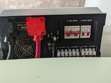
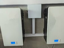
I currently have a Growatt 12KWH SPF12000 system with 15 KWH of battery storage (3 batteries, each 5 KWH). We’re planning to upgrade our storage capacity to 35 KWH. However, the local supplier/installer might have removed all identifying information from our existing batteries.

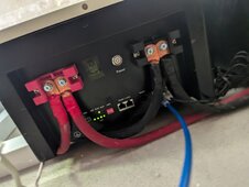
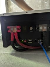
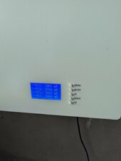
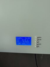
I've found a seemingly similar battery on Alibaba, but I believe ours might be an older version. The new model has a similar bottom end and a comparable screen/BMS setup.

Before purchasing an additional 20 KWH (2 batteries of 10 KWH each), I have a few questions:

  1. Battery Bank Configuration: If I get these new batteries, would I need to set them up as a separate battery bank?
  2. Main BMS Configuration: Should one of the new batteries act as the Main BMS?
  3. DIP Switch Limitations: The DIP switch on my current system, which I assume manages the order of the batteries, only goes up to 4. Can I daisy chain more than four batteries together, or is there another method to integrate the new batteries with the existing ones?
Thank you for your assistance.

Link to Alibaba Battery

 
Critical that you purchase the same nominal voltage - 48V (15 cells) or 51.2V (16 cells). You can determine this from your charge voltage.

48V/15S will only go to 54.75V max.
51.2V/16S will go to 58.4V max.

Even if the batteries aren't communication-compatible, you can still connect the new batteries in parallel with the old at their terminals to gain the extra capacity. The State of charge will still be mostly correct after several cycles.
 
+ (Battery 1)
|
+ (Battery 2)
|
+ (Battery 3)
|
+ (Battery 4)
|
+ (Battery 5)
|
+---- Positive to Load/Inverter

- (Battery 1)
|
- (Battery 2)
|
- (Battery 3)
|
- (Battery 4)
|
- (Battery 5)
|
+---- Negative to Load/Inverter


So something like this right
 
Critical that you purchase the same nominal voltage - 48V (15 cells) or 51.2V (16 cells). You can determine this from your charge voltage.

48V/15S will only go to 54.75V max.
51.2V/16S will go to 58.4V max.

Even if the batteries aren't communication-compatible, you can still connect the new batteries in parallel with the old at their terminals to gain the extra capacity. The State of charge will still be mostly correct after several cycles.

Forgive me if this is a basic question, but I want to clarify something regarding the Battery Management System (BMS).

Wouldn't the BMS be responsible for controlling the state of charge and ensuring the health of the batteries? If so, wouldn't it make sense to either connect all batteries to a single central BMS or have each battery bank managed by its own BMS?
 
+ (Battery 1) +---- Positive to Load/Inverter
|
+ (Battery 2)
|
+ (Battery 3)
|
+ (Battery 4)
|
+ (Battery 5)


- (Battery 1)
|
- (Battery 2)
|
- (Battery 3)
|
- (Battery 4)
|
- (Battery 5)
|
+---- Negative to Load/Inverter
usually suggested to take from the top of the positive and bottom of the negative or vice versa I e. kitty corner, otherwise battery 5 will have more of the load than the others.
 
Forgive me if this is a basic question, but I want to clarify something regarding the Battery Management System (BMS).

Wouldn't the BMS be responsible for controlling the state of charge and ensuring the health of the batteries? If so, wouldn't it make sense to either connect all batteries to a single central BMS or have each battery bank managed by its own BMS?
Each battery should be managed by its own BMS.

If you can do closed loop communications between the batteries and the inverter, you can get tighter integration between charging and discharging and reading the approximate state of charge and things like that. However, it sounds like that’s not easy in your case.

Open loop a.k.a. just using voltages, is a perfectly valid way of running your system. The All In One will charge up to your batteries one hundred percent voltage state, the BMS in each battery will equalize the cells, and when you put a load on the parallel batteries, they will contribute an appropriate amount to the inverter.
Oh I thought a BMS had to manage X amount of batteries hmm, there was a point where one of the batteries fell behind, and it just charged up the first two batteries to 100 percent and then stopped the other at 60 percent. Not sure if it just lost communication with the main one and fell behind. Thank you
 
Oh I thought a BMS had to manage X amount of batteries hmm, there was a point where one of the batteries fell behind, and it just charged up the first two batteries to 100 percent and then stopped the other at 60 percent. Not sure if it just lost communication with the main one and fell behind. Thank you
A battery management system manages all of the cells in a particular battery.
 
A battery management system manages all the cells in a particular battery.
Gotcha, I will contact our rep and see if I can get some more information on how the system is set up. Because I am not sure if they are doing closed loop, which might be the case because there are Ethernet cables connecting them from the inverter then to one another, and I am seeing online where the dip switches are used for identifying the battery in the system. So I might have misunderstood what is purpose is for because couldn't we do 16 combinations on 4 dip switches, meaning 16 IDs?
 
Gotcha, I will contact our rep and see if I can get some more information on how the system is set up. Because I am not sure if they are doing closed loop, which might be the case because there are Ethernet cables connecting them from the inverter then to one another, and I am seeing online where the dip switches are used for identifying the battery in the system. So I might have misunderstood what is purpose is for because couldn't we do 16 combinations on 4 dip switches, meaning 16 IDs?
Sounds like closed loop and you could have up to 16 IDs (batteries), though they’d all have to be the same protocol (mfr). Pictures?
 
Sounds like closed loop and you could have up to 16 IDs (batteries), though they’d all have to be the same protocol (mfr). Pictures?

Not sure if these are good enough, let me know if you need additional information / pictures
 

Attachments

  • Inverter BMS COnnection.jpg
    Inverter BMS COnnection.jpg
    144.6 KB · Views: 13
  • First Battery.jpg
    First Battery.jpg
    145.3 KB · Views: 12
  • Final Battery.jpg
    Final Battery.jpg
    91.2 KB · Views: 13
  • Battery Voltage Range (4).jpg
    Battery Voltage Range (4).jpg
    94.1 KB · Views: 12
  • Battery Voltage Range (3).jpg
    Battery Voltage Range (3).jpg
    95.7 KB · Views: 11
  • Battery Voltage Range (2).jpg
    Battery Voltage Range (2).jpg
    79.9 KB · Views: 11
  • Battery Voltage Range (1).jpg
    Battery Voltage Range (1).jpg
    93.4 KB · Views: 13
  • Battery Info.jpg
    Battery Info.jpg
    93.5 KB · Views: 13
  • Battery Front.jpg
    Battery Front.jpg
    160 KB · Views: 11
  • Battery Almost Full Voltage.jpg
    Battery Almost Full Voltage.jpg
    100.5 KB · Views: 13
Last edited:
Yeah, looks like you could add more if you knew what they were. No other identifying marks? Nothing in the battery (BMS) menus that tells you firmware or anything?
 
Yeah, looks like you could add more if you knew what they were. No other identifying marks? Nothing in the battery (BMS) menus that tells you firmware or anything?
Nope nothing at all, the only thing I can think of outside of asking, was to pull them but 1 i dont feel like it,2 I dont want to damage it really
 
Yeah, looks like you could add more if you knew what they were. No other identifying marks? Nothing in the battery (BMS) menus that tells you firmware or anything?
I am going to try to login directly to the inverter via the shine bus app and see if I can see the battery model or comm protocol
 
I am seeing where we used L51 for BMS Protocol which am assuming is CAN

Based on the manual I just found on page 6
 

Attachments

  • 1519017-manual.pdf
    2.7 MB · Views: 4
Looks like you need to switch the cable lugs that attach to the batteries for the narrow version. The pictures show them not laying flat.
 
Yeah, looks like you could add more if you knew what they were. No other identifying marks? Nothing in the battery (BMS) menus that tells you firmware or anything?
I do see Welcome to Smart BMS on startup which seems to be an actual name for a BMS lol
 
According to our test, it's not recommended to parallel battery with different capacity.
Normally 5kwh model comes with 100A BMS and 10kwh model with 200A BMS, that means different parameters like charging/discharging current or sth others. In this case, there will always be a SOC gap(Some customers mind it a lot).
So if possible, set up a separate system.
This will be news to many many members here
 
Not sure if these are good enough, let me know if you need additional information / pictures
From the looks of this the batteries are connected together but I'm not 100%sure they're connected through the correct com ports to talk to each other.
Not sure how comfortable you are with doing it but my suggestion would be to remove the front plate from one of the batteries and take a photo of the BMS we should be able to identify it then.
 

diy solar

diy solar
Back
Top