diy solar

diy solar

Need Help. New but humble enough to take your advice. I only know so much but I am really stuck. Need solid advice.

neoseven

New Member
Joined
Jul 16, 2024
Messages
14
Location
alberta
Hello everyone. New to the scene but very excited to really work this thing out and finally be able to have a way to cool some food. Let me start off by telling you a bit about my situation. I purchased a moble home under forclosure a year and 1 month ago. It was bad. 18 pipe breaks and 1000sqft of mold and fungus under the floor and a lot of mold and rot in the walls over the past 50 years. The wiring was done by a blind goat and the layout was nothing short of a 99% fire hazard. So bad i had to rebuild and shingle the roof and demolish everything underneath and build new. Ya load bearing walls and all. Massive project to do at 39 by myself, but im 65% of the way to having a solid mold free space.

The thing that is killing me is my 1 year old and 4 year old plus my partner can't stay in the city with me no more. I spent $35k in hotel fees to keep them close but unfortunately I ran out of money. So 16 long and agonizing days ago I had to send them away to my moms 5000km away. So I have been sleeping in my truck and going back to the good old days of 17 year old me. Broke and alone. I have managed to get some funding together. Ah I wont lie just using credit and racking up debt. I was able to purchased some stuff over the years and recently. Ill write a list below and take some photos. My goal is to hopefully soon be able to run my mini fridge non stop. I know I can run it off my bank for 3 days but I have no way to charge it. Lucky I have a bunch of stuff. I believe im 80% of the way to completing my own off-grid system.

This forum pops up all the time and everyone seem to be on point when it comes to helping the less informed. I am that less informed. Now dont get me wrong I am a master of common sence and dont argue when I am told I dont know a damn thing. That is my que to listen so I want to ask everyone to help me with what I need to do. So I dont have to hit the grocery store everyday and waste a ton of food, and fuel.


List of items I have :

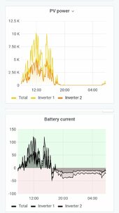
4x Odyssey Extreme AGM 2250CCA 100ah battries w/ 80% safe depletion @ 400 cycles (batteries are connected in parallel with 600v #6 welding wire, solid copper 3/8 connectors and solid copper 3/8 washers) (this bank ran my fridge for 3-1/2 days before dying) add 250watts for my laptop and lights) so about 2- 1/4 solid days of continuous power.

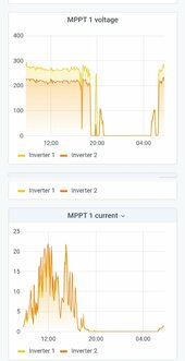
Victron 150/45 MPPT solar controller w/BT

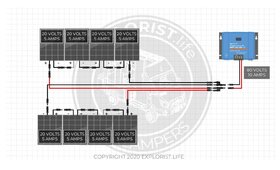
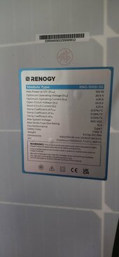
8x Renogy 20.4v/24.3v 100w solar pannels (specs in photo) (#14/2.5mm - wire)

Dewalt 1000w / 2000pw 12v inverter (works to power fridge, lights, and laptop - tested and works flawless)

#12 Pv 1500v wire @ 100ft w/15 male and female water proof connectors

1x 175amp fuse (may need smaller port since its 00 gauge)

I have also purchased 1240ah 48v worth of 320ah 3.2v 8000cycle batteries 68 in total. I am going to build a new system once I get a bit more set up and some money coming in so i can spend a small fortune on a few BMS systems.

I need to know with what I got the schematics of what I need to do to get this system up and running. I need reliable power and soon because the end is near if I dont.

Thanks for all the future help.
 

Attachments

  • 20240716_182447.jpg
    20240716_182447.jpg
    61.9 KB · Views: 4
Last edited:
Welcome to the forum.

I'd probably start drawing out a diagram of how you plan to wire everything up so you can get feedback on it.
If that's what I had laying around I'd wire the panels up 4s2p to the victron mppt, connecting the MPPTs to the battery first of course. I would connect all 4 batteries in parallel.
I'd get a set of good bus bars to make things easier.
I'd post a photo of the fuse so we can tell you if it's good or bad.
Head over to suncalc.org and get an idea of where the best location for your panels will be.

I'm sure others will chime in with much better advice and detail. I need to get some sleep so I can give better advice...
Free bump for you.
Thank you so much for the reply. I also want to mention if I need anything I will buy it as well. I do not want to cut any corners.
 
Dont know if any of this is useful.
Looks like you have plenty to get started. I wouldn't trust those fuses or the plastic breaker, they are designed for car audio.
I'm not sure on the titan 40A breakers.

The 8AWG will be undersized for your inverter primary connections. You could probably get away with using it to parallel the batteries to a buss bar then upgrading to a heavier cable for your main leads.

It looks like an inline blade style fuse on the PV wire?

Will has a pile of useful info on his website https://www.mobile-solarpower.com/, I'd look through the diagrams and recommendations.
The wire I am using for the battries is #6 welding wire rated at 600v @ 75amps. From the pannels will also be #6 welding wire since that is the max my charge controller can handle. None of the stuff I have in the photo other than the charge controller I need to use just provided it incase its useful since I am not using any more than 75 amps my inverter i think is only rated for 14.3amps. Remember this system is only using that dewalt inverter. It going to power laptop lights, and mini fridge. My 48v 1240ah system on the other hand will be 10x PHENex PS-M108HCBF-400w BiFacial module with a 450/100 - tr charge controller. Solar grid is going to be reflective under the pannels. This will be my main system then I will move the AGM grid to my garage.I just need physical conformation that everything I am doing on this AGM setup is fail safe x10. I want contingency after contingency. I have read alot of diagrams but for someone who is not sure its like reading sanskrit.
 
Last edited:
The wire I am using for the battries is #6 welding wire rated at 600v @ 75amps.
You could see more than 75A if you max out the inverter and the batteries are at a low soc (state of charge). It will probably be fine and I'd use it for a temporary setup.
From the pannels will also be #6 welding wire since that is the max my charge controller can handle.
I think you mean from the mppt to the batteries / DC bus. You will be fine using the 12awg you have from the panels to the mppt if you parallel them at a combiner box before the mppt.
None of the stuff I have in the photo other than the charge controller I need to use just provided it incase its useful since I am not using any more than 75 amps my inverter i think is only rated for 14.3amps.
The 14.3A is the AC output side. It was confusing for me at first keeping track of the AC vs DC side.
14.3A x 120VAC = 1716W
1716W ÷ 12VDC = 143A. (That would only be under a very brief surge).
Remember this system is only using that dewalt inverter. It going to power laptop lights, and mini fridge. My 48v 1240ah system on the other hand will be 10x PHENex PS-M108HCBF-400w BiFacial module with a 450/100 - tr charge controller. Solar grid is going to be reflective under the pannels. This will be my main system then I will move the AGM grid to my garage.I just need physical conformation that everything I am doing on this AGM setup is fail safe x10. I want contingency after contingency. I have read alot of diagrams but for someone who is not sure its like reading sanskrit.
You will be fine on the 12V side using what you have, I would upgrade the breakers and fuses or just use a quality breaker.
I like overkill so I'd use a fuse and breaker / disconnect on the panel strings, preferably something din rail mounted in a combiner box. I'd pick up some Midnite or other quality breakers for the batteries and run a quality fuse between the batteries and inverter.

I hope that makes sense and I'm not confusing you more.

If you search for board builds you'll probably find some great visuals to help.
Something like this that @HRTKD shared a while ago.
 
Thanks for all the info i have some questions now. I am dumbfounded on some stuff and i may feel stupid after getting the answer but i really want to know.

Ok hear goes.

I hear alot about 12v 24v 48v 72v etc i get the basics of it. but when its about a battery grid i loose all sense of understanding and get overwelmed.

So i know the higher the voltage the cheaper and smaller equipment you need. Cheaper lines, devices, and faster charging. but what stumps me is after that. If i run my pannels in series say 24.3 VOC x6 if i do a S3x2P. So technically a 3S x2 that would = 5.21amp Isc @ 145.8 Voc for my grid. Or im wrong and its 72.9 Voc @ 10.42amp Isc. Either way my MPPT should do its job @ 150/45. Now my battery bank is 12v so it down volts the input to output 12v. So my confusion is now that i have 72.9 or 145.8 i get 100watts @ 145.8voc or 200watts @ 72.9voc. Since the charge controller is only using 12v would it be a waste of the other 4-5 pannels if the batteries are only getting 12v at 100w to 200w. Would it not be obvious to only run in parallel so i can get the total 600w of power yes at a higher amp Isc is like 31.26amp but my charge controller is 45 so yes the pannels are 20.4N 24.3Voc. But now i am charging at a higher amp and full potential of the 600 watts. I hope your not confused.

Also say i have a 48v battery bank run 4P and run 2 sets in series in my 36voc pannels to get the 72v voc so say each pannel is 400w and i have 8. So i would get 1600watts at 76v more than enough to chrage my 48v grid. Now that the system is complete and i have 60v running into my controller and its charging my 48v bank. Great now how do i run 120v appliances off the 48v bank with out having to dump another 5k in dc to dc and inverters and stepdowns. It does not make sense. Would it not be more efficent to just get a fuse pannel some breakers and run slightly higher volts than your bank and just get thicker gauge wire to run your circuit. That way you get enough voltage yes higher amps but you are not getting a crazy amount of wasted energy??
 
Thanks for all the info i have some questions now. I am dumbfounded on some stuff and i may feel stupid after getting the answer but i really want to know.

Ok hear goes.

I hear alot about 12v 24v 48v 72v etc i get the basics of it. but when its about a battery grid i loose all sense of understanding and get overwelmed.

So i know the higher the voltage the cheaper and smaller equipment you need. Cheaper lines, devices, and faster charging. but what stumps me is after that.
I wouldn't necessarily say cheaper. For example I would use Class T fuses for a 48V battery bank and above, they aren't 'cheap' add in a quality disconnect/ breaker for the higher voltage and costs go up even more.
Your wire and cable could be less expensive due to the potential for a smaller diameter because of reduced current.
If i run my pannels in series say 24.3 VOC x6 if i do a S3x2P. So technically a 3S x2 that would = 5.21amp Isc @ 145.8 Voc for my grid. Or im wrong and its 72.9 Voc @ 10.42amp Isc.
In series voltage multiplies, amperage stays the same. In parallel amperage multiplies, voltage stays the same.
So in a 3s2p panel config you'd have 3x24.3V and 2x5.21A; 145.8V and 10.42A.
Either way my MPPT should do its job @ 150/45.
Be very careful and research the impact of cold temperature on panels. I would never run a 145VOC string on a 150V mppt in PA. You'll be well over 150VOC in cold temps. Will has a pretty great video that explains this.
Now my battery bank is 12v so it down volts the input to output 12v. So my confusion is now that i have 72.9 or 145.8 i get 100watts @ 145.8voc or 200watts @ 72.9voc. Since the charge controller is only using 12v would it be a waste of the other 4-5 pannels if the batteries are only getting 12v at 100w to 200w. Would it not be obvious to only run in parallel so i can get the total 600w of power yes at a higher amp Isc is like 31.26amp but my charge controller is 45 so yes the pannels are 20.4N 24.3Voc. But now i am charging at a higher amp and full potential of the 600 watts. I hope your not confused.
A little confused ...
The point of the MPPT is to find the maximum power point and step it down to battery charging voltage and maximize the charging power.
Some MPPTs have different max wattage ratings at different voltages, if they are capable of multiple charging voltages to begin with.
Also say i have a 48v battery bank run 4P and run 2 sets in series in my 36voc pannels to get the 72v voc so say each pannel is 400w and i have 8. So i would get 1600watts at 76v more than enough to chrage my 48v grid. Now that the system is complete and i have 60v running into my controller and its charging my 48v bank. Great now how do i run 120v appliances off the 48v bank with out having to dump another 5k in dc to dc and inverters and stepdowns. It does not make sense. Would it not be more efficent to just get a fuse pannel some breakers and run slightly higher volts than your bank and just get thicker gauge wire to run your circuit. That way you get enough voltage yes higher amps but you are not getting a crazy amount of wasted energy??
See above about how the mppt works.
You wouldn't need a DC to DC converter or stepdown. Your MPPT would charge the 48V bank, your inverter would power your 120VAC appliances by converting your 48VDC bank to to AC.
 
Ok ill try to simplify it a bit. Hopefully there is no confusion in what I am assuming. Ill keep it really simple. Say I have 48v solar array in parallel say just 2 pannels @ 800 watts each. So 48v 1600 watts. On paper since is 48v its 4x the wattage. So 1600w x 4. Say i have a 3000 watt 24v inverter. My battery bank is a 10x AGM 12v 100ah. That I have it configured into 24v at 500ah. Now isn't my charge controller nerfing what ever voltage it does not need to charge the 24v battery array? and only letting 24v pass through. Isn't that extra 24v of power being wasted? I would still be getting 3200watts, but 48v @ 1600 watts is 6400watts. So if the charge controller is nerfing it to 24v im loosing 3200watts of potential energy. if I do not have a 48v battery bank. I dont see the point if i only wanted to run a 24v 3000watt inverter. Why would anyone increse voltage just to loose your pannel wattage when it passes through the charge controller. The charge controller is not storing the extra energy. And at 24v its only 3200watts not 6400watts.
 
Last edited:
Ok ill try to simplify it a bit. Hopefully there is no confusion in what I am assuming. Ill keep it really simple. Say I have 48v solar array in parallel say just 2 pannels @ 800 watts each. So 48v 1600 watts. On paper since is 48v its 4x the wattage. So 1600w x 4. Say i have a 3000 watt 24v inverter. My battery bank is a 10x AGM 12v 100ah. That I have it configured into 24v at 500ah. Now isn't my charge controller nerfing what ever voltage it does not need to charge the 24v battery array? and only letting 24v pass through. Isn't that extra 24v of power being wasted? I would still be getting 3200watts, but 48v @ 1600 watts is 6400watts. So if the charge controller is nerfing it to 24v im loosing 3200watts of potential energy. if I do not have a 48v battery bank. I dont see the point if i only wanted to run a 24v 3000watt inverter. Why would anyone increse voltage just to loose your pannel wattage when it passes through the charge controller. The charge controller is not storing the extra energy. And at 24v its only 3200watts not 6400watts.
The mppt charge controller takes the higher PV voltage and reduces it to the system voltage while increasing charging current. You don't lose wattage unless the charge controller limits it at lower voltages.

You may be thinking of PWM controllers, I'm talking about MPPT.

Hopefully someone else can explain it in more detail.

I attached some charts from my system that may help explain it better.
 

Attachments

  • IMG_20240718_074140.jpg
    IMG_20240718_074140.jpg
    55.9 KB · Views: 3
  • IMG_20240718_074031.jpg
    IMG_20240718_074031.jpg
    48.7 KB · Views: 3
The MPPT is like a buck voltage regulator that steps down a higher voltage at low current to a lower voltage at higher current, with hardly any inefficiency loss, analogous to how a transformer can convert 120 VAC to, say, 5 V without a wastefully huge efficiency loss. However, unlike the transformer, the MPPT works with DC, actually by chopping it at a high frequency and using inductors and/or capacitors to smooth out the chops and to store the energy in a way that can come out at lower voltage. One more thing, the source (the panels) vary in both voltage and current supplied at the maximum power point depending on the seasons, clouds and shade, and the MPPT, ("Max Power Point Tracking") dutifully assesses this fact and adjusts itself to perform the conversion at this max power point for maximum efficiency, constantly.
 
I really appreciate all the knowledge. But for a minute lets go back to my first post and realize i am a 2 year old trying to figure out if the square fits in the circle. A lot of this stuff your saying is not in english. Its in Zulu. Simplify it that a 2 year old can understand. I just need a simple answer to my problem. Hence why I am asking these questions so i can figure out what is happening. I really want to fully understand from baby steps to full out mad scientist.

Disclaimer : I did not know how my truck worked, and did not want to pay for a mechanic. So i learned how 10,000 parts functioned and what their pourpous was and how everything went back together to spec. Now I can rebuild/Frankenstein engines, transmissions, and everything automotive or mechanical with zero pocket bolts. So be patient with me and I will be a diy solar engineer by the end of this year with no lack of understanding. That being said there is a lot a jargon I dont get yet. So I am going to ask some questions and hopefully I can get some direct answers that I feel confident I will never have to ask again. Not saying your all not answering them to the best of your abilities. Im just not there yet. I am sure I will go back to previous conversations and say wow you did answer my question.

I am going to spend some dough on a 3000watt 6000 peak 24v inverter.

Q: what size wires will I need for my battery bank? (Battery bank will be wired to 24v 2S2P as of now #6 welding wire 75a 600v this wire I think is for AC never had heat issues at max load, but you tell me what I need)

Q: I have 8x 100w pannels @ 20.4v/24.3v - 4.91A/5.21A (all wired with #14 PV stock)
What configuration do I put them in and how many can I use to get full potential? (My controller is Victron 150/45)
Q: what connectors do I need and what gauge wire do I need? ( I have a bunch of PV #12 with lots of MC4 connectors)
(I have 2x 1 to 4 split connectors MC4)

Q: I will buy what ever is needed for breakers and fuses so please tell me how many i need and what size AMP to use? And where in line they go in the system?

Q: What fail safe contingency do I need even if I dont really have to. Where do they go in line in the system?

Q: I may or may not be installing these on the roof or build my own solar tracker and mount a rotational frame to a post. What is the distance to energy loss and how do i compensate the loss? Do i use larger wire, etc? The longest hypothetical run would be about 50ft. That would be from the fuse/breaker pannel to the charge contoller (charge controller max wire size is #6).

Although I have victron products i want to fail safe every in and out so my system does not grenade if something fails. Remeber once i get a few bms I have 16x 3.2v 320ah 8k cycle batteries that I will make into a 24v system that will replace the AGM I am using now. And 48 more I will be using for my other system once I figure out how to get this up and running. So this system will need to be transferable.

Also if you can explain why they go there and what they do and the safety reasons for it. Would be a big help for me to get the full picture. I really want to learn this. I am building a massive compound and underground bunker with a 200KW bank in the next few years. So this little system will be the building blocks for the mother of all DIY solar grids.

Enviromental info:

Alberta, Canada

Temps: (temps are violent here avarage 10c - 20c difference from one day to the next. I have seen it -5c the next day -35.)
Summer: 20c to 35c
Winter: -5 to -45max

Sky: We get like 310 give or take clear sky days a year. And a stupid amount of solar radiation. Optimal for a solar grid. So much so that your skin will burn on a -30 day with the sun out. Very dry cold/heat). Lots of dead dinos in the area.

Wind: my property is not very windy below roof top so not really much concern for damage. Everything will be installed over engineered.

Wet/Moist: lol we are not Vancouver. So rain is maybe 15-35 days out of the whole year. Every year it changes so lets say a good 35 rain days a year.

I do want to mention this is a moble but it is still a house and there are saftey and building codes. Its fixed to concrete screw piles and a concrete pad underneath. The property is like 120-130 ft long and 50ft wide. I own the land outright and its in the city. I dont know how I am allowed to go off grid but I can.

Any info I missed please ask me to clarify and I will do to the best of my abilities. I need this system completed asap so I need a plain and to execute it this week or i am royally screwed.

Again I really thank everyone for your time. On the flip side I will help you with what ever mechanical problem you have as a sign of gratitude.
 
Last edited:
The MPPT is like a buck voltage regulator that steps down a higher voltage at low current to a lower voltage at higher current, with hardly any inefficiency loss, analogous to how a transformer can convert 120 VAC to, say, 5 V without a wastefully huge efficiency loss. However, unlike the transformer, the MPPT works with DC, actually by chopping it at a high frequency and using inductors and/or capacitors to smooth out the chops and to store the energy in a way that can come out at lower voltage. One more thing, the source (the panels) vary in both voltage and current supplied at the maximum power point depending on the seasons, clouds and shade, and the MPPT, ("Max Power Point Tracking") dutifully assesses this fact and adjusts itself to perform the conversion at this max power point for maximum efficiency, constantly.
Ok this is very good information. I did not know it has capacitors. That is good to know the MPPT is not just regulating the voltage to only pass through battery voltage and discharging extra voltage. So i guess my question how much loss would i get if my pannel array was on a 48v string. Would the MTTP store a large amount of energy in the capacitors or would there be some waste if any? Nominal voltage is like 20.4v per pannel so technically its only 40.8v powering the MPPT. And I do understand that you need to have more volts incase there is a big drop in sunlight or fluctuations in weather. More is better I see that now.
 
Last edited:
Looks like you have plenty to get started. I wouldn't trust those fuses or the plastic breaker, they are designed for car audio.
I'm not sure on the titan 40A breakers.

The 8AWG will be undersized for your inverter primary connections. You could probably get away with using it to parallel the batteries to a buss bar then upgrading to a heavier cable for your main leads.

It looks like an inline blade style fuse on the PV wire?

Will has a pile of useful info on his website https://www.mobile-solarpower.com/, I'd look through the diagrams and recommendations.
Yes MC4 connections. They all are MC4.
 
Will this work with out fuses? Pannels are 20.4/24.3 4.91A/5.21A charge controller is 150/45 so it looks like ill have lots of room. Then i can wire my battery pack to 24v or 48v and get a 24/1200 or 48/1200 victron. My issue i dont fully understand is if i get a 24v or 48v inverter how do i run 120v appliances. I am looking at getting a mini split so i may need two of this inverters. And a bigger controller.

Thanks
 

Attachments

  • Series-vs-Parallel-Solar-Panels-Amps-vs-Volts-14-1536x933.jpg
    Series-vs-Parallel-Solar-Panels-Amps-vs-Volts-14-1536x933.jpg
    62.2 KB · Views: 4
Will this work with out fuses? Pannels are 20.4/24.3 4.91A/5.21A charge controller is 150/45 so it looks like ill have lots of room. Then i can wire my battery pack to 24v or 48v and get a 24/1200 or 48/1200 victron. My issue i dont fully understand is if i get a 24v or 48v inverter how do i run 120v appliances. I am looking at getting a mini split so i may need two of this inverters. And a bigger controller.

Thanks
It will work, I would still add a breaker/disconnect.
If/when you add a 3rd string I would definitely add fuses.

The inverter will take the DC battery voltage and convert it to AC for your household loads.
The MPPT takes the "high" voltage from the panels and converts it to battery voltage.
 
It will work, I would still add a breaker/disconnect.
If/when you add a 3rd string I would definitely add fuses.

The inverter will take the DC battery voltage and convert it to AC for your household loads.
The MPPT takes the "high" voltage from the panels and converts it to battery voltage.
It will work, I would still add a breaker/disconnect.
If/when you add a 3rd string I would definitely add fuses.

The inverter will take the DC battery voltage and convert it to AC for your household loads.
The MPPT takes the "high" voltage from the panels and converts it to battery voltage.

Does not really explain anything. My pannels fuse rating is 15amps so as long as i do not exceed this rating a fuse will not work. I will get a breaker for the pannels just so i have a safe way to shut them off. But from how it looks in the photo that inline fuses are not required for this configuration as other configurations have fuses. I think inwatched a video on that even if 10 amps run through the pannel it will not burn up. I dont know why diodes are not installed on each ine of the pannels. That way it would be impossible for anthing to run back into the pannel.
 
Does not really explain anything. My pannels fuse rating is 15amps so as long as i do not exceed this rating a fuse will not work. I will get a breaker for the pannels just so i have a safe way to shut them off. But from how it looks in the photo that inline fuses are not required for this configuration as other configurations have fuses. I think inwatched a video on that even if 10 amps run through the pannel it will not burn up. I dont know why diodes are not installed on each ine of the pannels. That way it would be impossible for anthing to run back into the pannel.
Once you get to 3 strings or more you want fuses, 3 strings would put you over 15A that your panels are rated for.
I understand diodes but can't explain them that well.
 
Ok this is very good information. I did not know it has capacitors. That is good to know the MPPT is not just regulating the voltage to only pass through battery voltage and discharging extra voltage. So i guess my question how much loss would i get if my pannel array was on a 48v string. Would the MTTP store a large amount of energy in the capacitors or would there be some waste if any? Nominal voltage is like 20.4v per pannel so technically its only 40.8v powering the MPPT. And I do understand that you need to have more volts incase there is a big drop in sunlight or fluctuations in weather. More is better I see that now.
Typical MMPT efficiencies are in the high 90s of percent, even 98 or 99% - hardly any of the input power is lost. The MPPT actually doesn't need to store "a large amount of energy" if the switching frequency is high. Say an MPPT is converting 1000 W of solar into 990 W of output (i.e. at 99 % efficiency). If it did this conversion once per second, it would need to store a kilojoule of energy each time. But it the chopper ran at 1 kHz it would only have to store 1 joule, because it can pass each joule 1000 times a second, consuming the entire kilowatt input. If the MPPT chopped at 1 MHz, then it would only need to store 1 millijoule, which energy it passes a million times a second, to make up the kilowatt. I would not say the latter case is "storing a large amount of energy". But, I don't know what frequency they actually operate at.

The way buck converters work is that they can only make an output voltage that is less than the input voltage. So, if you want to charge a battery with, say, 14 V, and you use a buck converter, then the input has to be at least that much for the converter to work at all, hence the limitation.

More input voltage is better, up to the destruct voltage of the MPPT, keeping in mind that panels produce more voltage at low temps, and not only do you not want to destroy your MPPT on an ordinary day, you don't even want to destroy it on a really really cold day. So there should be some voltage headroom between the Voc of the panels and the destruct voltage of the MPPT. -40 degree temps happen where I live once in a while, at which point panels will be producing something like 1.25 of their nominal rated Voc, so I have to account for that in sizing a string for an MPPT, or in sizing an MPPT for a string. Of course your situation may be different.
 
Will this work with out fuses? Pannels are 20.4/24.3 4.91A/5.21A charge controller is 150/45 so it looks like ill have lots of room. Then i can wire my battery pack to 24v or 48v and get a 24/1200 or 48/1200 victron. My issue i dont fully understand is if i get a 24v or 48v inverter how do i run 120v appliances. I am looking at getting a mini split so i may need two of this inverters. And a bigger controller.

Thanks

The Array you posted will be 80vdc @ 10amps

The Inverter goes 24vdc or 48vdc TO 120vac

So 24v or 48v DC “inverted to”’120v AC


What City in Alberta ? From that you can obtain some historical Sun Harvest data & figure out what you might be able to harvest @ what time of year.


Can You post a schematic drawing of what you are trying to put together ?? That would be a big start to this process.

800W array divided by your battery charge voltage will give you your charging amps.

@ 24v battery max array is 1300W
@ 48v battery max array is 2600W


IMG_0968.jpeg
 
Last edited:
Disclaimer : I did not know how my truck worked, and did not want to pay for a mechanic. So i learned how 10,000 parts functioned and what their pourpous was and how everything went back together to spec. Now I can rebuild/Frankenstein engines, transmissions, and everything automotive or mechanical with zero pocket bolts. So be patient with me and I will be a diy solar engineer by the end of this year with no lack of understanding. That being said there is a lot a jargon I dont get yet. So I am going to ask some questions and hopefully I can get some direct answers that I feel confident I will never have to ask again. Not saying your all not answering them to the best of your abilities. Im just not there yet. I am sure I will go back to previous conversations and say wow you did answer my question.
I admire your tenacity. That said, don't be discouraged if you figure out that solar is not as easy to grasp as more mechanical things are. I came to solar having extensive previous experience with satellite dish installations, television cabling and cable headend design, computer networking, and house/business electrical wiring, not to mention having completed nearly half of CIE's electrical technician course, having a technician class HAM radio license, and an FCC station operator license. I never imagined solar would be so complicated as it has turned out to be for me!

I spent at least five months researching various aspects of the solar system before I felt comfortable beginning to make purchases. Even after having put together a working system, I still feel rather ignorant about many parts of it. I worry that, due to some minor thing of which I was ignorant or which I had overlooked, the system will fail--possibly in a big way (e.g. with a bang).

I would say, from my humble level of experience, that understanding the following items is crucial for any beginner to get started.

  • Volts versus amps and how series versus parallel affect them
  • Wire sizes and amperage requirements
  • Resistance and its relationship to heat
  • Surface area and proper contact at junctions to accommodate high-amperage loads
  • Solar panel production as a function of temperature and solar incidence angle
  • Inverter limits with respect to solar input (read the manual!)
  • Efficiency and product availability for various voltage systems: 12v, 24v, 48v, etc.
  • Inverter compatibility with resistive loads, inductive loads, and capacitive loads
  • High-frequency (HF) versus low-frequency (LF) inverters: what's the difference?
  • Purpose and effectiveness of fuses, and fast-blow versus slow-blow fuses
  • On-grid, hybrid, and off-grid systems
  • Various battery chemistries and their unique properties: e.g. NiCd, lead-acid (flooded), AGM, LiFePO4, NMC, etc.

And yet there is so much more! Add to the list such "trivial" things as correct torque settings, fitting proper lugs to cables, whether or not to use a paste in the joints, which metals to trust and which to avoid, dangers of mixing different metals, AC versus DC currents and their impact on breakers, weaknesses inherent to certain products/manufacturers, which businesses/suppliers are trustworthy versus which ones will cheat you or charge too high a price for their brand, warranties, etc. I even got sucked into tangents during the course of my study like whether or not to use a locking washer! (Research shows they can actually loosen the nut, instead of helping to keep it tight.)

So much to learn! If you enjoy learning, it will be a fun experience for you. If not, you may wish to stick to ready-made solutions of some sort.
 
Once you get to 3 strings or more you want fuses, 3 strings would put you over 15A that your panels are rated for.
I understand diodes but can't explain them that well.
AS I UNDERSTAND IT....

Some people get away with three strings, fuseless....but it's a risk. It depends on how resilient your panels are. In theory, having three strings means having three separate electrical sources, which are combined. As long as they produce equally, there is no problem: but if one is shaded, and not producing, it becomes "weak" and the two stronger panels overpower it and push their current through it. If the solar cells are capable of handling double their usual current, this may not be an issue...but if not, they can be damaged by the excess current.

Most people, having three batteries, would not desire to mix two good ones with one older, partially discharged battery for similar reasons--the new batteries would just push some of their current into the weaker battery, instead of all three helping to power the device. Batteries may or may not be damaged in the process, but fuses are used between solar panel strings to protect them from potential damage.

Two strings is safe without fusing because either string should be able to handle the amount of current it is itself able to produce, as would be supplied by the other string.

Now, if I've misunderstood any of this or explained it poorly in my "laymen's terms," I'm open to correction as well.
 
Typical MMPT efficiencies are in the high 90s of percent, even 98 or 99% - hardly any of the input power is lost. The MPPT actually doesn't need to store "a large amount of energy" if the switching frequency is high. Say an MPPT is converting 1000 W of solar into 990 W of output (i.e. at 99 % efficiency). If it did this conversion once per second, it would need to store a kilojoule of energy each time. But it the chopper ran at 1 kHz it would only have to store 1 joule, because it can pass each joule 1000 times a second, consuming the entire kilowatt input. If the MPPT chopped at 1 MHz, then it would only need to store 1 millijoule, which energy it passes a million times a second, to make up the kilowatt. I would not say the latter case is "storing a large amount of energy". But, I don't know what frequency they actually operate at.

The way buck converters work is that they can only make an output voltage that is less than the input voltage. So, if you want to charge a battery with, say, 14 V, and you use a buck converter, then the input has to be at least that much for the converter to work at all, hence the limitation.

More input voltage is better, up to the destruct voltage of the MPPT, keeping in mind that panels produce more voltage at low temps, and not only do you not want to destroy your MPPT on an ordinary day, you don't even want to destroy it on a really really cold day. So there should be some voltage headroom between the Voc of the panels and the destruct voltage of the MPPT. -40 degree temps happen where I live once in a while, at which point panels will be producing something like 1.25 of their nominal rated Voc, so I have to account for that in sizing a string for an MPPT, or in sizing an MPPT for a string. Of course your situation may be different.
That is very good information. I absorbed it all at a 100% efficiency rating lmfao. All jokes aside the MPPT is still witch craft but I understand its function. So i guess my grid at the worst case scenario would be 121.6voc in the 4S2P configuration. Still way under the 150 rating of my MPPT. So for this array i should have no issues, but I did say transferable so the extra insight is useful for future projects. Since I am only 2 string and its 8.6A nominal then I would be less than the 15 amp fuse rating. So I will not need a fuse. I still want to look into why a diode is not used inline since a diodes main function is to only allow current one way. I think the pannels have diodes pre-installed in the sealed box on the back of the pannel.
 
The Array you posted will be 80vdc @ 10amps

The Inverter goes 24vdc or 48vdc TO 120vac

So 24v or 48v DC “inverted to”’120v AC


What City in Alberta ?


Can You post a schematic drawing of what you are trying to put together ?? That would be a big start to this process.

I’m from BC, but will be in Alta tomorrow.

800W array / 12vdc = 66 amps

But

800W array / 13 vdc = 61 amps

But

800W array / 14 vdc = 57 amps

You have a 150 | 45 ?? ,, That is 45 amps max ,,, you are leaving some amps on the table ,,, probably ok
Edmonton

Ya controller will only max out at 122voc and 11amp round up. So it would be well within its limit. I may be able to add a few more pannels and keep the voltage the same and ad a string or 2 but like mentioned I would be over the 15 amp fure rating and will need inline fuses or a pannel. I am more interested in were the fuses go for the battery bank and how to fail safe the system incase of a current run away. I have heard it happens so fast the fuse cant blow in time and it hits your battries at full voltage. I know Victron is good but there should always be contingencies.
 

diy solar

diy solar
Back
Top