diy solar

diy solar

WARNING! Major Issue With 18Kpv, Exporting to Grid for hours when Not Programmed To!

When you say grid tied are you simply referring to the inverter being connected to the grid. So, what if I never want to sell back but would like to take advantage of grid charging and grid assist should battery reserves not be adequate for said load/s...i.e. a cloudy day. Are CT required despite no intention of selling back and having it checked off in the firmware? If so, isn't this a design flaw?

Are other inverters like this or is this specific to EG4?
I *think* i understand the logic . Take for example the gen input. If a generator is connected all loads are taken by the generator.

Without cts, i think the grid would follow the same logic, ie all loads taken by the grid. Which means the inverter wouldn't take anything from battery or pv to support the loads, rendering the inverter essentially unnecessary.
With the CTs, grid relay is still connected but inverter can inject power to reduce grid draw.

Not all inverters are like this. Victron ess for example. It can use grid , battery and pv together to power loads on the load output without an energy meter connected.
 
Have you tried out without the cts?


So it the amount of load even when it's just passing through grid to load? Pretty cool.
Yeah the amount of data this this thing logs is pretty extensive. Won't be able to efficiently analyze it on a laptop for sure.

Just from playing around with the settings and menu, I can say 18Kpv was programmed as a grid tie inverter first and formost. = Off-Grid Mode Disable.
This mode is likely the most stable. Even though there is risk (of surge export), it seems to be well defined.

The scenario I encountered seems to be such a one off that I have not been able to duplicate it. There are a few more things I can try and then it's beyond me.

The discharging of batteries in the middle of night scares me though. The reason it stopped was due to another mode programmed to kick in at 7am. I wonder if the unstable mode was left to continue what would happen? Would it continue to ramp current? Run til low V cutoff?

What if I was gone a few days and forgot to check in? What if it ended up discharging 5,10,15kWh to the grid.... this is what I have been staring at for a week... = strained eyes.
 

Attachments

  • 20240725_204858.jpg
    20240725_204858.jpg
    232.2 KB · Views: 13
Last edited:
My memory is not great, but didn't someone have a problem something like this before. And someone recommended they use a chargverter and discontinue the 18Kpv grid side connection.
There was this thread https://diysolarforum.com/threads/t...eturning-and-replaced-with-sol-ark-15k.66786/
I believe that poster said he could not keep it from back feeding and ended up going back to a Sol-ark which worked correctly.

I would not be surprised to see inverter manufactures start giving disclaimers when connecting a hybrid inverter to the grid you must have a interconnect agreement with your utility they won't be responsible for back feeding illegally I think the CT clamps work but not 100%. Although the post I linked above he said it does work correctly on the Sol-Ark. IMO I wouldn't do it illegally just asking for trouble only takes one call to the AHJ and an inspector is at your door. Just get the interconnect agreement and permitted, or use an offgrid inverter and a transfer switch.
 
I would removed the CT's ( disconnect the RJ45 ) and see what if anything changes, could help pinpoint the cause if software or hardware.
I was the one whom suggested for testing to disconnect the CT's
Just from playing around with the settings and menu, I can say 18Kpv was programmed as a grid tie inverter first and formost

There is no real "off grid mode" and connected to grid, it's exclusive. if the inverter is connected to the grid, everything comes into play on energy flow and is all software regulated.

First and foremost, one needs to understand that with all Hybrids, the CT's are only used for "system" energy values, all hybrids have measuring there output internally, CT's are there for seeing tar loads ( loads other than the backup loads ) as well controlling paralleling units. To have the CT's measuring only the output of the unit would then have two measurements each with there own tolerances providing slightly different results in the 1-3% range. If this setup is not specifically tested, one could have the potential of weird oscillations with divergent values from two sources on the same measurement point.

Also, "enabling charging" and setting to zero is another issue, one has to understand with these high power devices, resolutions even with 1% your looking at hundreds of watts of error, and CT's are not 1%.

My best guess is your trying to run in a mode that the measurement's can't provide due to tolerances of the monitoring hardware.

If your goal is to find the issue, you have to go into test mode and start experimenting, so start with removing the CT's and then with them connected, move them to the grid feed on the main panel
 
You are arguing perhaps theres none, but then add.... there could be more than seen.
Agreed. Which is the entire point I've been trying to lead you to. Your data does NOT support your claim.
Once again, you are seeing what you *want to see* in the data, not what it is *actually telling you*
 
This continually confuses me. If you no-how, no-way want the thing to export to the grid, why are you connecting it to the grid?

To IMPORT from the grid. He doesn't have any solar hooked up to it yet and is using it like a UPS and battery time-shifter. (High rate time: Run the loads from the batteries (up to the max inverter capacity, then mix in utility power if there's more load than the inverter can handle). Medium rate time: Run the loads from the utility. Low rate time: Charge the batteries and run the loads from the utility. NEVER feed power from the batteries to the utility.

(Actually: And after he couldn't get it working right at his customer's site he's switched his customer to another brand inverter and got this one hooked up at his shop with "the utility" being a breaker on his shop's main panel, while trying to help SS & EG4 get this figured out, before throwing in the towel on the EG4 version of this model and shipping it back for a refund.)

Hybrid inverters in "grid assist mode" tie the utility input to the main output (like simpler inverters in bypass mode) but also run the inverter driving the output, too. They let the utility set the inverter's frequency and have the inverter push the voltage until it's supplying all the load's power, or as much of it as it can, but no more. It monitors the current to/from the utility with the external current transformers, so it can know how much output is too much and make that adjustment.

The current transformers for utility input are external (unlike all the other inputs/outputs) so you can hook it up:
utility -> current transformers -> non critical loads panel and utility input of inverter -> inverter -> critical loads panel
and then the inverter makes enough power to run both the critical and non-critical loads (or as much of that as it can manage).

Unfortunately the feedback from the current transformers isn't accurate enough, or fast enough in responding to big load changes (like motor starts/stops), to guarantee that you NEVER end up pushing some power toward the grid in this configuration. So it typically deliberately errs on the side of pulling a little juice from the grid (maybe a couple hundred watts) to avoid a long-term backfeed. For load-drop spikes it just has to react fast and hope the utility's equipment doesn't report it. (Normal operation of some loads also backfeed for a short time, e.g. some elevator designs or motor speed controls, which act like regenerative braking on an EV to scavange energy on slowing down, stopping, lowering weight, etc., so utilities give SOME slop for short backfeed events.

If utility power dies, but the disconnected "island" of customers has enough generation (from this and other inverters etc.) to cover its loads and keep running, the frequency will quickly start to drift. When it goes out of (very tight) spec the inverter detects this, takes over frequency control, and opens the relays connecting utility line input to output (i.e. goes into stand-alone / off-grid mode). The inverter now powers the critical loads, but stops sending power to the non-critical loads and toward the utility's island. As all the other inverters, etc. (if any) feeding the island do the same thing, the island collapses, the non-critical loads go dark, and linemen don't get killed by surprise shocks from the supposedly unpowered neighborhood as they try to fix things. (The inverter may have an input from an emergency generator, which it starts and either sets it to recharging the batteries at the same time they're being discharged into the inverter or maybe does the same bypass-relay, let the other guy set the frequency trick with the generator, once it's stabilized and the inverter has gotten into frequency and phase sync with it.)

When the grid comes back the inverter first waits a few minutes (typically 5) for the line to stabilize, then synchronizes its output with the line, closes the bypass relays and goes back into grid assist mode.
 
Last edited:
There is no real "off grid mode" and connected to grid, it's exclusive. if the inverter is connected to the grid, everything comes into play on energy flow and is all software regulated.
The 18kpv is able to do this and it works perfectly for me.
Off grid mode opens the grid relays but the inverter still monitors and sync's to grid. IF it overloads (good luck with that) it will close the relays and grid will help it with the load. It is still monitoring the load and when it returns to a level the inverter can handle, the grid relays open.
Also if the battery gets too low, again it will close the grid relays and charge the battery plus pass through power for the loads.
Again when the battery is charged sufficiently, the grid relays open and it's back to fully off grid.
 
To IMPORT from the grid. He doesn't have any solar hooked up to it yet and is using it like a UPS and battery time-shifter. (High rate time: Run the loads from the batteries. Medium rate time: Run the loads from the utility. Low rate time: Charge the batteries and run the loads from the utility. NEVER feed power from the batteries to the utility.

(Actually: And after he couldn't get it working right at his customer's site he's switched his customer to another brand inverter and got this one hooked up at his shop with "the utility" being a breaker on his shop's main panel, while trying to help SS & EG4 get this figured out, before throwing in the towel on the EG4 version of this model and shipping it back for a refund.)
Note that ksmitha1 said "If you no-how, no-way want the thing to export to the grid".
Not "why would you connect". The AIOs are not perfect. Many of us can get away with that, I can for example because I am still on an analog meter.
But if you absolutely can't have export at the risk of being caught, don't use a setup that could export.
 
The 18kpv is able to do this and it works perfectly for me.
Off grid mode opens the grid relays but the inverter still monitors and sync's to grid. IF it overloads (good luck with that) it will close the relays and grid will help it with the load. It is still monitoring the load and when it returns to a level the inverter can handle, the grid relays open.
Also if the battery gets too low, again it will close the grid relays and charge the battery plus pass through power for the loads.
Again when the battery is charged sufficiently, the grid relays open and it's back to fully off grid.
You get absolutely no accumulated export?
My Sol-Ark does the same, but it has a hard time, especially with a partly cloudy day. If there is a heavy load and PV is going in and out, it sometimes exports for a second. It simply has a hard time during yo-yo.
 
I was the one whom suggested for testing to disconnect the CT's


There is no real "off grid mode" and connected to grid, it's exclusive. if the inverter is connected to the grid, everything comes into play on energy flow and is all software regulated.

First and foremost, one needs to understand that with all Hybrids, the CT's are only used for "system" energy values, all hybrids have measuring there output internally, CT's are there for seeing tar loads ( loads other than the backup loads ) as well controlling paralleling units. To have the CT's measuring only the output of the unit would then have two measurements each with there own tolerances providing slightly different results in the 1-3% range. If this setup is not specifically tested, one could have the potential of weird oscillations with divergent values from two sources on the same measurement point.

Also, "enabling charging" and setting to zero is another issue, one has to understand with these high power devices, resolutions even with 1% your looking at hundreds of watts of error, and CT's are not 1%.

My best guess is your trying to run in a mode that the measurement's can't provide due to tolerances of the monitoring hardware.

If your goal is to find the issue, you have to go into test mode and start experimenting, so start with removing the CT's and then with them connected, move them to the grid feed on the main panel
I tried siggesting that too (disconnect cts) but op didnt seem at all interested in trying it and @Markus_EG4 came on and said you need the cts connected.

🤷🏻‍♂️
 
Last edited:
For those of us following this who may not be as knowledgeable about this stuff. This scenario makes sense to me but I never really thought about what happens in this small time frame (milliseconds?) What would happen in this scenario if it was an off grid install. Just solar panels, battery bank, inverter, charge controller. And just to be a little more specific, lets say it is an all Victron setup with 2 Quattro 48/10,000kVA inverters in split phase 120V/240V, Victron MPPT RS 450/100 and throw in a cerbo and a shunt if it matters. Where does that energy go when the inverters are chugging away and a large load shuts off, like a stick welder on thick steel?
@green mountain boys this is an excellent question, and a significant difference between "offgrid inverters" and "hybrid inverters"

At the end of the day, electricity requires a difference in potential to "flow". If there is nowhere for the current to go, it doesn't go anywhere. This is the same reason that you can take a 10kw PV array.. and if you only have 200w of loads, that array will only produce 200 watts (satisfying the load, but no more.. in this scenario, we're ignoring batteries and such as additional loads)

offgrid inverters are the same concept. They'll produce as much as they can up to their software or hardware limits, if there is enough differential/load. But, a 10kw inverter will only "produce" 200w, if there is 200w of load. There is nowhere else for the energy to go.

The situation changes on a hybrid inverter. By it's very nature, it's connected to the grid which is essentially an unlimited amount of load (when given the example of "inverter has a large load shut off". In this case, the power output is being controlled by software rather than potential... Software will *always* take some amount of time to react to varying loads. Usually this is in milliseconds, but it *can* be longer. When connected to the grid, this manifests itself in having varying amounts of power "leak" back to the grid. Utility companies understand this, which is why nobody has ever heard of a utility contacting a user for leaking back 3000w for a few milliseconds or similar.

Now, some people try to prevent the "leaking back for a few milliseconds" thing, by telling their inverter to always draw X amount of power. In theory, this would work. But in practicality, most people try to "always draw" small amounts. 100 to maybe 500 watts. So while the theory is sound, the reality is.. a large load shutting off will STILL leak a bit of energy to the grid.

At the end of the day.. If you have no intention of ever selling to the grid, and simply CAN NOT have energy power leak back under any circumstances then you should probably buy an offgrid inverter, or verify that your hybrid inverter has an offgrid mode that you can enable that physically disconnects the grid (which also means you'd need enough solar and battery to actually operate the loads without the grid)

Short of that, every hybrid inverter has this "leaking" behavior.
The always draw part is an issue. I have mine set to the recommended 20 watt setting. That's sufficient 95% or more of the time. But I've had export spikes of over 1k (High PV, dryer turning off). So I'd have to have my always draw above that. During the summer, I could probably disconnect my grid, so that last thing I want to do is draw any more than I have to. Again, for me, not an issue, analog meter, who will ever know.
 
Agreed. Which is the entire point I've been trying to lead you to. Your data does NOT support your claim.
Once again, you are seeing what you *want to see* in the data, not what it is *actually telling you*
I think you are missing the fact that OP has continuous loads in the grid panel, that are GRID SIDE/UPSTREAM of the CT sensors.

His CT sensors are positioned BETWEEN these loads and the 18Kpv, so that with zero export settings, even if there are small periods of surge that momentarily "sell" through the CTs, those will be absorbed by the upstream loads before the "sell" power even makes it to the grid meter. The fact that the POCO shows zero load for a length of time, means there was indeed reverse current through those CT sensors!

He has all the data there for you. You are the one not seeing it! You have accused him of seeing what he wants to see, but the fact is that the data he provided proves his point.

A few points:
  • Main grid panel loads are in place (upstream of CTs) to absorb momentary reverse current through CTs and avoid actual sellback to POCO
  • CTs logged "sell-back" (via 18Kpv) note* see my screenshot below, from the very first post by OP showing the chart!
  • 3rd party CT sensors logged "sell-back" similar to 18Kpv data (if I understand correctly)
  • All the "sell-back" noted above is power flow from 18Kpv to main panel, pushed out through the CTs that are supposed to be the data point where 18Kpv does not sell past!
  • The fact that POCO data shows zero for a length of time, confirms that there was continuous power flow from 18Kpv, through CTs, to main panel.
  • Please note that regardless of actual sell/sold power to POCO, there is a problem with power pushing back through the CTs to main panel! OP has configured 18Kpv to NOT SELL, but it did in fact "sell" a significant amount of power out through CT sensors!
Real quick and in short now:
  • 18Kpv says power was "sold" (registered current through CTs, of course)
  • 3rd party energy meter says power was "sold" (again out through 18Kpv's CT sensors)
  • POCO says zero load on panel UPSTREAM from CT sensors for a period of time
I think it's time to stop accusing OP of only seeing what he wants to see!

Side note* OP has been sarcastic and touchy, but I would be sarcastic and touchy as well if I were him. OP has also not always been as quick to fully cooperate in things such as getting pictures for SS as he probably should have. (Sometimes we "Professionals" overlook simple things, so we need to always follow directions when a tech support persons asks us to check the simple things! Personally, I have made a fool of myself on a few occasions, due to missing small simple things, dumb things!) I'm definitely not saying he shouldn't listen to what people have to say! But I think he has given evidence to support his claims, and the fact that Eg4 and/or Luxpower are digging in deeper is also evidence that they feel this was an actual issue as well!

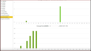
note* Power to grid logged by 18Kpv (CT sensor data), screenshotted from OP's first post.

1722001201044.png
 
This continually confuses me. If you no-how, no-way want the thing to export to the grid, why are you connecting it to the grid? Put in a transfer switch to a load panel feed the ATS from the grid or the inverter.
What if you want to use the inverter as a power source and backup i.e. whole house or sub panel. I was wanting to get a small inverter to drive a sub panel where my deep freezers, well pump and a few other things reside. I'm wanting to connect the inverters AC input to the main panel so it can use the grid when needed for charging the batteries on cloudy days and make up for battery resources needed when trying to run/start a load. I think this was called grid assist by some. I'd like to configure the inverter to use the pv and battery input to drive the sub panel but also have access to grid power from the main panel ....but never export. In the previous scenario wouldn't the inverter "exporting" back feed into my main panel? Now I have two sources of power at the main panel that are most likely out of phase...I see this causing major issues. Is this correct?

If the above is correct then I'd wager it's a big deal past the concern of getting a ticket from the power company ..you can kill a lineman or you can destroy the electronics in the house or fire etc.

I was looking at one of these units or the midnite one but I'd be connected to the main panel and don't want to back feed it.
 
The 18kpv is able to do this and it works perfectly for me.
Off grid mode opens the grid relays but the inverter still monitors and sync's to grid. IF it overloads (good luck with that) it will close the relays and grid will help it with the load. It is still monitoring the load and when it returns to a level the inverter can handle, the grid relays open.
Also if the battery gets too low, again it will close the grid relays and charge the battery plus pass through power for the loads.
Again when the battery is charged sufficiently, the grid relays open and it's back to fully off grid.
That sounds almost exactly what I want for my alternate location, what are the basic settings to set this up?
 
This is all very interesting as we are in the process of installing a NON SOLAR UPS as a Whole House UPS using same pattern as the OP.

No solar panels can be installed, EG4 12kPv or 18kPv is in the plan with a hefty battery (TBD) connection and a Honda EU7000 to charge batteries once they are depleted while grid remains down

Now, a little scared of how to proceed with all this information !
 
No, the inverter will synchronize itself to the grid before it connects to it.
So, if the inverter is being fed from the main panel by say a 50amp breaker it will sync up with the other src, grid in this case, before trying to back feed? If so I guess that resolves the out of phase issue but still doesn't protect a lineman if the grid goes down. If you choose to not export in the settings it should be a given it won't for multiple reasons.


Thanks OP for bringing this up!
 
The one inverter does not send energy to the grid ( same model / manufacture ) and the other does, is not a fact will always not sell as production run of products there is variances, the tolerances of the CT are very poor and since they haven't been removed for a test or swapped out we have no idea how far off they are from actual reported parameters of one is faulty.

I don't believe EG4's warning the CT's must be connected ( that is a tech helping, not an engineer ), all hybrids have fully instrumentation on the grid port for the digital control loops, it is impossible to use CT's as the internal loop control, it is orders of magnitude slower, it would never work in anything but stead state operation.

The OP has a use case that doesn't work for him. This requires some testing of different configurations to pinpoint the cause. If your not willing to do the testing, it won't get fixed.

For the Solis S6's I have as an example, they have unit power limits and then CT ( system ) power limits for the exact reasons I wrote above, they run fine with or without external CT's as they have too. I use both as I have parallel units but Duke energy has a hard 10K sell back limit. Using the CT's only, edge of cloud and other dynamic events will over shoot selling, so I use per unit limits ( percentage of rated power ) which is very fast response and CT's for system level to keep below the 10K sell limit as best as can be done.

BTW, I a previous life I worked on both inverters and charge controllers and wrote code for control loops. There is also digital filtering, which one can use tools to prioritize response vs stability, its all a big challenge of finding the best overall solution and when you start getting products deployed, edge cases will pop-up like these.
 

diy solar

diy solar
Back
Top