jjww
Stuck in PG&E Land
No, but I do have an open grid tie request hung up with the whole PCS debacle with the 18KPoco hasn't said anything to you?
(since February 2024)


No, but I do have an open grid tie request hung up with the whole PCS debacle with the 18KPoco hasn't said anything to you?
Holey crap not the dreaded PCS on the 18Kpv........Are you guerilla or on parallel operation with no inadvertent export?
PG&E allows the latter so presumably SCE probably would too. In PG&E one flavor of it is called "Option 10: Non-Export with Inadvertent Export Utilizing Certified Power Control Systems" (I have Rule21 open in front of me at the moment to be pedantic)
This is all very interesting as we are in the process of installing a NON SOLAR UPS as a Whole House UPS using same pattern as the OP.
No solar panels can be installed, EG4 12kPv or 18kPv is in the plan with a hefty battery (TBD) connection and a Honda EU7000 to charge batteries once they are depleted while grid remains down
Now, a little scared of how to proceed with all this information !
It will disconnect from grid as per 1741 regs, but still monitors it for return and stability of the grid.Try or will not? Do or do not..there is no try!
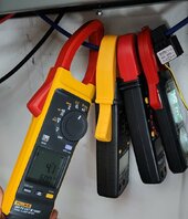
I highly doubt it's CT location. The logs show multiple data points that do not line up. The measurements or calculations taken eslwhere is what I would look at.As Markus mentioned in this thread, it seems to be a data miscalculation due to the CT placement in the system. We also noticed that AC charging was enabled with 0 kW, and then 0.1 kW on separate occasions. This low charging power, combined with the CT placement, could be causing the issue. Although our engineering team is investigating this, I wouldn't raise any alarms just yet. I don't foresee any issues with your setup if it's installed according to the recommended diagrams.
Then explain how this works:...... it is impossible to use CT's as the internal loop control, it is orders of magnitude slower, it would never work in anything but stead state operation.
Then explain how this works:
We have tested this in R&D with an RGM meter that reads with 0.1% accuracy.
we use a lot of Chroma here. we have 1 Yokogawa analyzer that thing is a beast. You get what you pay for with then 100%20x times better that standard spec external meters used, I get this as I use own Yokogawa power analyzers for my design work, they were 0.25%
Markus, I pray the Power Co does not contact me about this. If they do I may have much bigger issues.Let's wait and see what the power company has to say. There's a lot of really useful information in this thread now. The only real truth will be the data provided by the power company. I can assure you that we have never been in any kind of dispute with a power company over selling back power before. We have tested this in R&D with an RGM meter that reads with 0.1% accuracy.
")
Modbus? We are talking (on Sol-Ark) 3,000:1 ratio CT sensors, with the secondary wires (twisted pair) going straight to a circuit board in the inverter. Then there is an internal set that is basically hooked in the exact same way, just at a different point in the inverter....Sure, its called latency. Internal measurements are done in microseconds, the CT's in seconds. The difference is what can cause unintended sell.
The CT's use a slow serial protocol called modbus, add in the internal processor and its delays and filtering and you get what it is.
Got that, many inverters use external meters that the CT's connect to, it eliminates the distant issues or the inverter having to be X feet from the mains. I'm a Solis HV guy now and it uses the Actel meter.Modbus? We are talking (on Sol-Ark) 3,000:1 ratio CT sensors, with the secondary wires (twisted pair) going straight to a circuit board in the inverter.
Got that, many inverters use external meters that the CT's connect to, it eliminates the distant issues or the inverter having to be X feet from the mains. I'm a Solis HV guy now and it uses the Actel meter.
Makes sense where you were coming from on that! Modbus would definitely bring latency into affect!6) I realize the scenario is likely frustrating to the OP, but "lashing out" at people in the forum is a bad look, and is quite offputting for others who may want to help. You may want to take a step back, breathe, count to 10, and refrain from posting those types of responses if you truly are asking for help. If you aren't and just want to air dirty laundry, then by all means, proceed as normal.
Agree, the response time on the 18Kpv is adequate to mitigate surges for minimal backfeeding, no problem. It can easily and consistently arrest sudden stop test loads of over 7kW so far. (AC + Airfryer + Microwave = low tech testing by pulling fuse and setting 1 min timer on airfryer and mic. Airfryer takes more than 1 min to heat up so heating element is pulling almost 2k power... my 120v outlet at that location is getting abused, lol. )Modbus? We are talking (on Sol-Ark) 3,000:1 ratio CT sensors, with the secondary wires (twisted pair) going straight to a circuit board in the inverter. Then there is an internal set that is basically hooked in the exact same way, just at a different point in the inverter....
There is absolutely not seconds of delay using external CT sensors! Even watching live (within 1-2 seconds) data remotely via Solar Assistant, I can clearly see the 15Ks of the previously mentioned site adjusting their output within a split second of power jumping or dropping!
I don't want to derail this thread further on this subject, but if you (or anyone else) would like to see this in action, I can get a video recording for you. Feel free to DM me, or direct me to a thread that would be suitable to discuss this further on!
No, this is not accurate. A "CT" is just a coil connected to a sensing unit it stands for "Current Transformer". The AC induces a small current that rolls down the wire to the sensor which can be as sensitive as you like. There are different flavors of CT's which vary the number of windings inside the unit, allowing for different scaling of the signal. I believe the 18K as a setting for this in the advanced screen, I'm not looking at it right now. The greater the current traveling down the wire the larger the magnetic wave coming off the wire, thus inducing greater current at the CT which is detected by the sensor.Sure, its called latency. Internal measurements are done in microseconds, the CT's in seconds. The difference is what can cause unintended sell.
The CT's use a slow serial protocol called modbus, add in the internal processor and its delays and filtering and you get what it is.
OI never wrote CT's don't work, they are the system ( home ) level measurements, and is relatively stable, until loads change. Nothing bad happens what loads change except for the energy movement can go places you don't want to ( grid in this case )
They are bidirectional, but agree with everything else. Something in the inverter opened the gates to allow my batteries to supply to grid.Apparently the CT's for these inverters is directional. Not sure how that works but it would be a requirement to know which way the power is flowing to shut it off. Electricity moves / is drawn towards the load (The receiver of the power) not forced out by source (The provider of the power). If you connect two sources to one load neither source is aware of the other. If the voltage in one source is lower than the other it will act like a load instead of a source. The funky frequency tricks/signaling is one of the ways backfeed is controlled by the power company in that scenario, but if you didn't catch an agreement that puts the box in front of your inverter it isn't going to know, and will allow a lower voltage grid to act like a small load. The only way to stop this would be to know that the grid was presenting a load by measuring the current flow traveling between the grid and the shared bus powering your internal loads.
I'm not sure why this concept is so confusing, but I think people do not understand how electricity travels. This same concept is the issue with balancing your cells in your battery bank when they are in parallel. You end up with batteries feeding each other when there is a voltage imbalance.
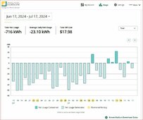
No forced discharged. This would be too easy to catch : ). It would show up readily in all the logs; raw data, line chart, bar chart. I have to specify these separately becasue the data is calc/gathered from different sources. I get frustrated EG4 keeps telling me my CT location is a likely culprit.Op, on the 18Kpv screen, app, or EG4 monitoring none of these have accidentally had force discharge enabled? Also I have had issues with force discharge disabled but time parameters set.
Agreed we supply Yokogawa flow meters on our skids at work they are great (different industry)we use a lot of Chroma here. we have 1 Yokogawa analyzer that thing is a beast. You get what you pay for with then 100%
Sorry for being slightly off-topic here.No, the CT does not send modbus, it is a dumb transformer. You hook a CT to a device that samples the CT output which is ANALOG. You could convert it to modbus, and send it to another device, but it is unlikely you would do that inside an inverter. I would bet dollars to donuts, that there is an ASIC inside the inverter that is handling the CT inputs making the real-time analog information available on demand from the ARM based CPU inside the ASIC. There is no necessity to convert to modbus and poll inside the asic, you would just read the register directly to get the last sampled value, likely updated every few milliseconds at worst. The sample rate can be whatever you want it to be, and the detector is watching for fluctuations in the produced wave.

You said it.AC Charge - Enabled, means the inverter should not draw from battery ( of course unless grid is down)
AC-Charge Power should not matter what setting is since above 2 would (should) prevent any sellback.
I just don't understand
Sir, I know exactly how it is Supposed to work. Post #92You said it.
To expand -
AC Charge - Enabled means it is allowed to charge from AC as well as solar.
AC-Charge Power is how much power it is allowed to draw from the grid to charge.