diy solar

diy solar

Wiring from LV5048 to breaker box for 50amp service outlet

jimjones26

New Member
Joined
Aug 20, 2020
Messages
74
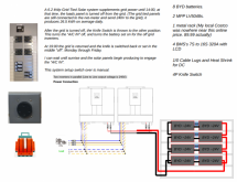
I have a HYBRID LV5048 Split Phase 120V/240V output 5kW 48V. I want to wire the LV5048 AC out into a breaker box, and from there provide (1) 50amp service to plug our camper into, and maybe (1) outlet to hook up a space heater to keep the cargo trailer where I am housing the LV5048 and batteries warm at night. All other outlet needs will come from the RV for now (the 50amp service). I am wondering about wire sizing from the LV5048 to the breaker box, and then what breakers and wire size from the 50amp service and the smaller outlet service. Also, will grounding to the steel frame of the trailer be enough, or should I drive in a ground stake where I end up putting the trailer?

Also I am wondering about adding breakers between all the different components (panels to LV5048, LV5048 to battery, ac input to inverter, ac output to panel). Manual states 45amp breaker between ac input and inverter, using 10awg cable. For solar panel cables it recommends 8 awg wire with a dc breaker between panels and inverter. It says typical amperage is 80A. I am guessing I need an 80A DC breaker here?

So that leaves the breaker between the inverter and the batteries and the main breaker in the breaker box. The product infor page for the LV5048 mentions it has a 60 A Utility Battery Charger (Will automatically charge your battery from Utility power in the event of low battery voltage). As far as I can tell there is no other mention of any additional chargers, so I am guessing a 60A DC breaker between the inverter and battery is what I need?

As far as the main breaker in the breaker box, I'm not sure, still researching.
 
Last edited:
Thank you for the videos, I had seen them before. Let me try and break down each part of the build and see if I can get some guidance that way.

Step 1: Gas generator to LV5048 AC Input
The manual states that a 40amp breaker should be used between the AC supply and AC Input on the inverter. The recommended wire gauge is 10awg.

As far as I can tell, I need the following items to complete this step:
1. Receptical to plug generator into
2. Wire from generator receptical to a load box
3. 40 amp breaker in this load box
4. Wire from load box to AC Input on inverter

For number 1, what outlet on my generator should be used? It has 50 amp, 30 amp, 20 amp, 15 amp and 13 amp outlets.

For number 2, I know I need 10 awg, I am guessing 10/4 is what I need?

For number 3, what is the cheapest option for a 40 amp breaker box that still allows for proper neutral and grounding connection?

Thank you all in advance for guidance on this first step.
 
1: use the 50 amp outlet on the generator
Use an RV extention and chop the receptacle end off, or just use 10-3 Romex. If you are using any kind of longer distance you can bump the wire to 8-3, but 10-3 is plenty for a 40 Amp circuit.

2: even though it is called 10-3 it does have 4 lines in the bundle. https://www.lowes.com/pd/Southwire-Romex-SIMpull-250-ft-10-3-Non-Metallic-Wire-By-the-Roll/3129315

3. Get a 60amp breaker box and populate it with what ever breakers you want. ?


Home Depot, Menards, Lowes, pretty much all the same. Never by cheap no name stuff. Inexpensive is not the same as cheap.
 
Thank you for the reply! So it seems I have two options for the 50amp input from the generator; either buy an rv cord, cut the end off and wire into the breaker box, or buy an inlet. As I am installing this in a 6x12 trailer and eventually will only use the generator on cloudy days, I think I want to go with an inlet recepticle. That will keep me from having a cord attached to the trailer permanently.


So from this recepticle to the breaker box, is 10/3 still an acceptable size?
 
I like this a lot (you just buy it and use it, ?:
Most heavy-duty RV cords are 10 awg, so a 10/3 is the same.


So, I think we are kind of getting wrapped around the axle.
Back to thinking of why using a Nema 14-50 extension cable. Cut both ends off and that is what you use to go to the input and the output of LV5048. Then you have the plugin end to connect to your box on the trailer, which is the loads panel for the trailer.

Use the other end as the input for whatever you want to power the AC when there is no Sun, generator or shore power.
 
Last edited:
I apologize, this is all really difficult for me to grasp for some reason. Let me recap for Step 1.

Instead of buying 10/3 wire, I could just buy a nema 14-50 extension cord. I cut off the male and female ends of the cord, and then use that wire for the AC input and output on the LV5048. For the input side, I run the wire from the LV5048 into the breaker box you suggested, which has a 40 amp breaker. From the 40amp breaker I could reconnect the male end that I cut off earlier.

That could work, if I can buy a weather proof box to mount on the outside wall of the 6x12 trailer, and mount the male end in that box securely.
 
Drawing things out on paper definitely helped! I have the AC Input and Output as well as the inlet and outlet needed for accepting power from the generator and delivering power to the RV. The Inlet and Outlet will be mounted on the outside of the 6x12, and I will run the lines through the wall to the inside.

Step 2: Batteries to Invertor
1. I need a DC breaker between the batteries and the LV5048, but I'm not sure what size. I need to figure out how to calculate this. A video online says he used 100amp breakers, but this calculation calls for 125amp. 5000 / 48 x 1.2 = 125 amps

2. The batteries I bought came with Anderson connectors. The wires they sold me are only 6 awg, rated to 200C. However, the LV5048 manual recommends 2*4 awg. Not sure what to do here. I am assuming the battery cables the battery manufacturer recommended are 6 awg because they are 24v batteries. I am combining 2 to get 48v pack. I will research more on this.

3. Box to hold the breaker. I am going to the local electrical supply store today and will find something there.
 
Last edited:
Page 5 of the manual indicates that the unit is expected to draw 220A off the battery. I would shoot for a 250A fuse and disconnect switch. The use of one of these
images


Is not recommended

to handle 220A @48v you'll need dual 4awg wires or a single 1/0awg as indicated on the same page as above. (note dual wires are typically not recommended due to safety concerns)
 
I like this a lot (you just buy it and use it, ?:
Most heavy-duty RV cords are 10 awg, so a 10/3 is the same.


So, I think we are kind of getting wrapped around the axle.
Back to thinking of why using a Nema 14-50 extension cable. Cut both ends off and that is what you use to go to the input and the output of LV5048. Then you have the plugin end to connect to your box on the trailer, which is the loads panel for the trailer.

Use the other end as the input for whatever you want to power the AC when there is no Sun, generator or shore power.
Hello All. My research has landed me to a similar solution with this same LV5048 inverter/converter. I have been reluctant to ask this question, as it is probably truly naïve (but I gotta know).

Is it advisable to hardwire the cut end of this https://www.amazon.com/gp/product/B07F47JC3M/ref=ppx_yo_dt_b_asin_title_o02_s00?ie=UTF8&psc=1 generator extension cord, as the ac input from a gas generator (when solar is not sufficient to charge batteries) and also use this https://www.amazon.com/gp/product/B074PWJVWC/ref=ox_sc_saved_title_6?smid=A3DS44SIO06CTJ&psc=1 adapter on that same cord to charge from a regular house receptacle?

As an aside that may be helpful to others: https://www.amazon.com/gp/product/B00A8FQUYW/ref=ppx_yo_dt_b_asin_title_o07_s01?ie=UTF8&psc=1 outlet panel
 
instead of cutting the plug off the generator cord, instead install one of these as your alternate way to get generator power to the "grid" side of the inverter.


You should also be useing a generator interlock with the above receptical. https://www.amazon.com/Square-Schneider-Electric-HOMCGK2C-Generator/dp/B00CONE4MG/ref=sr_1_3?dchild=1&keywords=generator+interlock&link_code=qs&qid=1604437575&sour ceid=Mozilla-search&sr=8-3&tag=wwwcanoniccom-20
Thank you. I actually already have something similar among my collection of things purchased for this ever growing "project" of mine. I will consider using it, instead of sending it back. The system will be off grid, so if I am understanding this correctly, the interlock wouldn't be necessary. As far as safety goes, If I wired the above to the ac input, would I be able to use the adapter to use household current to charge batteries (two 24 volt 50 ah battle borns in series)?
 
If I wired the above to the ac input, would I be able to use the adapter to use household current to charge batteries (two 24 volt 50 ah battle borns in series)?
If you wired the generator receptacle directly to the grid input on the MPP, the unit (if configured correctly) will use the generator power to charge the batteries. You need to ensure that the generator power does not "mix" with the AC power output of the inverter. This can be accomplished a number of ways.

You'll want to ensure that your grid-battery-charge-current setting does not exceed the recommended charge current for the BB bats.

You'll also need to pay special attention to the overvolt setting and undervolt setting on the MPP and ensure they are within the range of the BMS on the BB. (if the MPP is set to overcharge/overdischarge the BB, the batts will self-disconnect and, as the MPP unit is powered off the batteries, the system will shut down)

I also feel compelled to point out that your 24v 50ah BB are only rated for 60amps continuous discharge, were as the MPP has the capability to pull 200a+ off the battery. (you either have to much inverter for the batts, or not enough batts for the inverter)
 
I have pulled 160 amps out of my battery once. I did a max load test with everything I have turned on in the house. Normally it is drawing about 30 amps.

I use 1/0 cable for the battery terminal. There is a bolt and nut that you attach the cable to.
 
So I figured out I am going to have to rebuild the battery cables I bought using 1/0awg. The batteries have Anderson connectors built into the battery box. I have read that Anderson connectors are not really the best option, but I think I need to go with what I have right now.

As far as the 250 amp fuse and battery disconnect switch, does anyone have any recommendations?
 
The batteries I bought have sb175 Anderson connectors built into the battery box. The pole these connectors use is rated for 180 amps. I think this means if the inverter is trying to pull max amps from the battery, these 180 amp poles will be a weak link and could overheat?
 
The batteries I bought have sb175 Anderson connectors built into the battery box. The pole these connectors use is rated for 180 amps. I think this means if the inverter is trying to pull max amps from the battery, these 180 amp poles will be a weak link and could overheat?
 
The batteries I bought have sb175 Anderson connectors built into the battery box. The pole these connectors use is rated for 180 amps. I think this means if the inverter is trying to pull max amps from the battery, these 180 amp poles will be a weak link and could overheat?
You will never even come close to pulling 180 amps DC with one LV5048.. More likely max out at 85.

I have 2 MPP Solar LV5048S in parallel and the max DC I have ever seen is 165 amps.
 
Back
Top