diy solar

diy solar

YaYa needs wires and Fuses

CQLife

YaYa Gets Skooled
Joined
Oct 7, 2020
Messages
18
Location
North Carolina
Ok so I’m not certain about correct fuses and wires.
I’m building the 24v DIY system with 2-12v 200ah life PO in series
I have the 400w panel Renogy system 4x100w which I plan to series and parallel with 40a Rover MPPT.
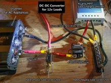
I will be going with the 24v 2000w inverter and the DC 24v to DC 12V 40A 480W Buck Transformer

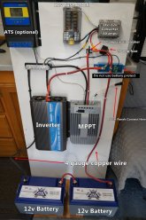
I’m unsure if I should use the recommended 50a circuit breaker or the provided 40a bolt on fuse between battery and MPPT. There seems to be a bolt on main fuse probably much larger in the second picture demonstrating his system since the Victron component is no longer being used. and should I use 4g wire for this or the provided tray cable aluminum looking wires that appear to be 8g. Which seems too small in reference to what Will suggested. One mor question is what size fuse between the bus bar and the converter?
Thanks in advance for the guidance. This is really holding up everything and I want it right.
 

Attachments

  • 540A5916-F5B3-4C5E-B0F0-06F636C4A542.jpeg
    540A5916-F5B3-4C5E-B0F0-06F636C4A542.jpeg
    96.1 KB · Views: 27
  • 602301E4-3748-4EBD-8E72-6F119C16058E.jpeg
    602301E4-3748-4EBD-8E72-6F119C16058E.jpeg
    134.1 KB · Views: 27
Thanks for your reply. I understand that alternator charging isn’t great on LiFePo4 batteries or I would have gone that route. But I will certainly look at the inverter/charger for future upgrade.
 
for a 2000 ac watts in a mobile setup I suggest you stay at 12 volts.

2000 ac watts / .85 conversion factor / 12 volts = 196 inverter dc amps
196 inverter dc amps + 40 dc amps = 236 total dc amps
236 total dc amps * 1.25 fuse headroom = 246 fuse amps

You should have a 250 amp main fuse as close to the positive battery terminal as possible.
You will need wire that can handle > 250 amps.
Suggest 3/0 or 4/0 welding cable.
The dc_2_dc_charger limits the amount of current your lifepo4 batteries can draw and thereby protects the alternator.
That breaker looks like an amazon special and those are scary.
Suggest you send it back and get a quality one from bussman.
this is a good place to get stuff like that https://www.waytekwire.com/products/1633/Marine-Rated-Circuit-Breakers/&Mounting-Style=Surface-Mount
As far as the rest it depends on how many of the suggestions I've already made that you wish to adopt.
 
That looks like a renogy dc_2_dc charger.
You should probably refer to this blueprint https://www.mobile-solarpower.com/simplified-400-watt-fewer-wires-and-alternator-charging.html

I take it this is a mobile setup, confirm?
If yes and you ever plan to connect to shore power I suggest you get a ul-458 certified inverter/charger.
I re-read these posts and realized you thought I had a dc-2dc charger. Here's what I have: 400w 12v (4x100)PV, Renogy Rover 40a SCC with provided tray cables (8awg), a 12v 200ah Lifepo battery, 9" 4/0 cables from battery to 300a ANL fuse to 2200w Giandel Inverter with the provided 5awg cables, 50a circuit breaker to 40a SCC and adding a DC fuse block which I'm planning to add a circuit breaker between ANL 300a and the fuse block.(wire size and breaker dependent on what I plan to load in the fuse block, is there a typical size? Led lights, compost fan and diesel heater are all I have so far) I did calculations as per your guidance (319a) and I definitely need a 300a fuse for this 2200w inverter. I hope this provides more accurate description. Still waiting on my amp reader to determine more exact loads. I want to make sure my cables are properly sized and fused. I am currently not set up for shore power. I will use inverter for my ac loads. The whole premise for me is to be solar. I intend to add more battery and panels in the future. Sorry for redundancy and I so appreciate your help.
 

Attachments

  • PS-2200KSC USER MANUAL 1904.pdf
    4.9 MB · Views: 5
I suggest you should have an alternate source of power because the sun doesn't shine every day.
https://www.renogy.com/12v-dc-to-dc-on-board-battery-charger/ is an option.

You should have a means of disconnect between the solar panels and the scc.
That will allow you to "turn off the sun".
I hope the breaker you mention is not a cheap amazon special.

In the following diagram "|" represents a busbar.
One for the positive leg and another one for the negative leg.
Code:
|<->300amp_anl_fuse<->battery.pos
|<-50_amp_circuit_breaker<-40_amp_scc<-disconnect<-panels
|<-fuse<-dc_2_dc_charger<-breaker<-starter_batter.pos
|->2200_watt_inverter
|->100_amp_fuse->dc_fuse_block->001_amp_fuse->shunt.pos

|<->shunt<->battery.neg
|->40_amp_scc->panels
|->dc_2_dc_charger->starter_batter.neg
|<-2200_watt_inverter
|<-dc_fuse_block
 
Last edited:
Thanks! I’m upgrading the circuit breaker to the one you recommended previously. I do have a bus bar off negative battery terminal. I will add a bus to the positive side.
“|->100_amp_fuse->dc_fuse_block->001_amp_fuse->shunt.pos”

i.e. 100a fuse from positive bus to dc fuse block to 001a fuse? Also Shunt.pos? I need a shunt here? I understand the rest of the code.


I also have a battery meter that came with a 100a shunt. But that attaches to the neg side I believe. My LiFePo4 battery has a built in BMS. Having the meter may be somewhat redundant since I think I can get that information from the Rover.

I will consider upgrading to a dc-to-dc charger. My plan was to have at least 3days of battery storage in lieu of a charger.
A 100 amp shunt is not big enough.
Here is one that will work https://www.amazon.com/AiLi-Voltmeter-Ammeter-Voltage-Motorhome/dp/B07FGFFHC6
The shunt goes between battery.neg and the rest of the system.
It also needs connection to the postitive side and that is the shunt.pos.
Its the small red wire in the diagram at the link above.
 
I suggest you should have an alternate source of power because the sun doesn't shine every day.
https://www.renogy.com/12v-dc-to-dc-on-board-battery-charger/ is an option.

You should have a means of disconnect between the solar panels and the scc.
That will allow you to "turn off the sun".
I hope the breaker you mention is not a cheap amazon special.

In the following diagram "|" represents a busbar.
One for the positive leg and another one for the negative leg.
Code:
|<->300amp_anl_fuse<->battery.pos
|<-50_amp_circuit_breaker<-40_amp_scc<-disconnect<-panels
|<-fuse<-dc_2_dc_charger<-breaker<-starter_batter.pos
|->2200_watt_inverter
|->100_amp_fuse->dc_fuse_block->001_amp_fuse->shunt.pos

|<->shunt<->battery.neg
|->40_amp_scc->panels
|->dc_2_dc_charger->starter_batter.neg
|<-2200_watt_inverter
|<-dc_fuse_block
Hello again! I wonder if you would have any modifications you would suggest to the code you gave me (above) since I’ve taken your advice and purchased a dc-dc charger. It’s the Renogy DCC50S 12V 50A DC-DC On-Board Battery Charger with MPPT. I’m planning on just swapping it out with my current 40a rover mppt. Then maybe use the 40 later on something when I add more power. I do have 2 12v paralleled starting batteries on my bus. I will run cable to the starter battery positive and I guess ground to the chassis with 4 awg. Thanks again.
Wishing you happy holidays!
 
Do not mount the inverter vertical with the fans or the other end up. Did you read your manual?
 
Hello again! I wonder if you would have any modifications you would suggest to the code you gave me (above) since I’ve taken your advice and purchased a dc-dc charger. It’s the Renogy DCC50S 12V 50A DC-DC On-Board Battery Charger with MPPT.
There have been a lot of problem reports with the DCC50S.
I no longer recommend it.

I will run cable to the starter battery positive and I guess ground to the chassis with 4 awg.
Using the chassis for a high current return path is very likely going to cause grief.
How many amps is your alternator rated for?
How many amps is the vehicle already drawing from it?
Based on these answers I think we might find you a better solution.

Wishing you happy holidays!
Same to you and yours. :)
 
Last edited:
There have been a lot problems reports with the DCC50S.
I no longer recommend it.


Using the chassis for a high current return path is very likely going to cause grief.
How many amps is your alternator rated for?
How many amps is the vehicle already drawing from it?
Based on these answers I think we might find you a better solution.


Same to you and yours. :)
Uh oh! Already purchased and begun installation. I have 2 195cca starter batteries in parallel. Haven’t been able to determine actual alternator amps yet. I also agree I should not ground to chassis. I’ve also re-wired my 4-100amp 12v panels in parallel and fused each with 20a fuses. I noticed my starter batteries are paralleled with 1/0 and connected with either 3/0 or 4/0 cables. Batteries are 2yr old lead acid and are working great.
 
Uh oh! Already purchased and begun installation. I have 2 195cca starter batteries in parallel. Haven’t been able to determine actual alternator amps yet. I also agree I should not ground to chassis. I’ve also re-wired my 4-100amp 12v panels in parallel and fused each with 20a fuses. I noticed my starter batteries are paralleled with 1/0 and connected with either 3/0 or 4/0 cables. Batteries are 2yr old lead acid and I currently do not have the recommended 80a circuit breaker to starter battery positive and only my previous 50a CB to the mppt pos. I was hoping to get set up before the rains come today in central NC. I’m currently running my diesel heater on my LiFePo4 which is disconnected from solar and some shore power for essentials until reconnecting. Any advice down this path would be greatly appreciated. (Other than spending loads more money ?
 
Apologies in advance for the big increase in complexity.
The charger has a common negative which makes the logic representation byzantine.
Code:
legend {
    eg { equipment ground }
    <-> { bi-directional flow }
    -> { uni-directional flow }
    <- { uni-directional flow }
    nnn|NNN| { an fused busbar position where nnn is the wire guage and NNN is the fuse rating in amps }
    nnn|UUU| { an un-fused busbar position where nnn is the wire guage }
}
battery {
    pos
    neg
}
fuse_block {
    upstream {
        pos
        neg
    }
    downstream {
        pos {}
        neg {}
    }
}
shunt {
    pos
    neg {
        upstream
        downstream
    }
}
inverter {
    pos
    neg
    eg
}
dcc50s {
    pos {
        out
        pv<-breaker<-panels.pos
        alt<-breaker<-starter_batter.pos
    }
    neg
}
system {
    pos {
        |<->fuse<->battery.pos
        |<-fuse<-dcc50s.pos.out
        |->fuse->inverter.pos
        |->fuse->fuse_block.upstream.pos
        |->fuse->shunt.pos
    }
    neg {
        |<->shunt.neg<->battery.neg
        |<-inverter.neg
        |<-fuse_block.upstream.neg
        |->panels.neg
        |<->dcc50s.neg
        |<->inverter.eg
        |<->starter_battery.neg
    }
}
 
There have been a lot problems reports with the DCC50S.
I no longer recommend it.


Using the chassis for a high current return path is very likely going to cause grief.
How many amps is your alternator rated for?
How many amps is the vehicle already drawing from it?
Based on these answers I think we might find you a better solution.


Same to you and yours. :)
Ah! Santa is good to me! I think I understand the code. I will diagram it and send you a copy. Thank you so much.
 
Apologies in advance for the big increase in complexity.
The charger has a common negative which makes the logic representation byzantine.
Code:
legend {
    eg { equipment ground }
    <-> { bi-directional flow }
    -> { uni-directional flow }
    <- { uni-directional flow }
    nnn|NNN| { an fused busbar position where nnn is the wire guage and NNN is the fuse rating in amps }
    nnn|UUU| { an un-fused busbar position where nnn is the wire guage }
}
battery {
    pos
    neg
}
fuse_block {
    upstream {
        pos
        neg
    }
    downstream {
        pos {}
        neg {}
    }
}
shunt {
    pos
    neg {
        upstream
        downstream
    }
}
inverter {
    pos
    neg
    eg
}
dcc50s {
    pos {
        out
        pv<-breaker<-panels.pos
        alt<-breaker<-starter_batter.pos
    }
    neg
}
system {
    pos {
        |<->fuse<->battery.pos
        |<-fuse<-dcc50s.pos.out
        |->fuse->inverter.pos
        |->fuse->fuse_block.upstream.pos
        |->fuse->shunt.pos
    }
    neg {
        |<->shunt.neg<->battery.neg
        |<-inverter.neg
        |<-fuse_block.upstream.neg
        |->panels.neg
        |<->dcc50s.neg
        |<->inverter.eg
        |<->starter_battery.neg
    }
}
If you don’t have time to get back to me until after Christmas I completely understand. I just wanted to respond with where I am. All my negatives including the eg for the inverter go to the neg bus bar with the 350a shunt from my house neg and then the neg on the dcc50s <-> goes to the bus bar. All my positives do the same and I have a 300a ANL between house pos and pos bus. I will have to wait for individual cir breakers for each connection you posted as “fused”. I’m currently only running diesel heater and intermittently the water pump on battery as I have some shore power. If I wait for cir breakers to connect the starter side shouldn’t I be able to utilize solar alone? (granted it will be raining the next few days.) Merry Christmas Smooth Joey.
 
If you don’t have time to get back to me until after Christmas I completely understand. I just wanted to respond with where I am. All my negatives including the eg for the inverter go to the neg bus bar with the 350a shunt from my house neg and then the neg on the dcc50s <-> goes to the bus bar. All my positives do the same and I have a 300a ANL between house pos and pos bus. I will have to wait for individual cir breakers for each connection you posted as “fused”. I’m currently only running diesel heater and intermittently the water pump on battery as I have some shore power. If I wait for cir breakers to connect the starter side shouldn’t I be able to utilize solar alone? (granted it will be raining the next few days.) Merry Christmas Smooth Joey.
Sorry, that is too much prose for me to parse with any certainty.
The postive leads from the solar panel and starter battery should go to their repective terminals on the dc2dc charger.

Merry Ho Ho!
 
Back
Top