


Greetings oh scions of solar. Virtuosos of voltage. Buffs of the BMS. I have a situation that is driving me wacky trying to troubleshoot. Perhaps someone has an idea for me ?- thanks in advance.
My Setup: Growatt 48v SPF 3000TL LVM, 16s 176AH LiFePO4, ANT SMART BMS
So after a month of waiting for my ANT SMART BMS to arrive (ordered off eBay from a Chinese supplier) , I was excited to get it all hooked up (and replace a DALY I had installed temporarily). The setup was pretty simple and straight forward. {Once you figure out to temporarily short the two black wires to get it to start ;-) } Everything was rocking and rolling and I was feeling good.
Well, for a moment.
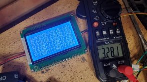
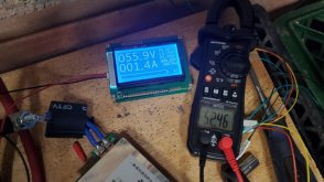
My Growatt was saying the battery voltage was 52-53V but the fancy LCD screen with the BMS was saying it was 56V. I assumed maybe there was some voltage drop between the battery and the inverter but it is pretty much 2AWG wire from battery to inverter so that didn't seem likely. I then took a multi-meter to each cell and they were all pretty much 3.3V but the BMS screen was reporting about 3.5V.
Anyone have any ideas what is happening here? Can it be a wiring issue if the BMS is reporting higher than the actual voltage. (.2V higher per cell and between 3-4V higher for the pack). The whole system is tied to the same negative so zero should be zero, right? The only thing I did notice when bringing everything only was that before the BMS was turned on I was getting approximately 4V between the battery positive and the C- lead on the BMS. I assumed that should have been 0V with the BMS still off but with everything sharing the same negative why would that make a difference.
To use a movie analogy, it seems like that scene in DieHard 2 when they reset sea level to -200ft so the ground wasnt really the ground.
My Setup: Growatt 48v SPF 3000TL LVM, 16s 176AH LiFePO4, ANT SMART BMS
So after a month of waiting for my ANT SMART BMS to arrive (ordered off eBay from a Chinese supplier) , I was excited to get it all hooked up (and replace a DALY I had installed temporarily). The setup was pretty simple and straight forward. {Once you figure out to temporarily short the two black wires to get it to start ;-) } Everything was rocking and rolling and I was feeling good.
Well, for a moment.
My Growatt was saying the battery voltage was 52-53V but the fancy LCD screen with the BMS was saying it was 56V. I assumed maybe there was some voltage drop between the battery and the inverter but it is pretty much 2AWG wire from battery to inverter so that didn't seem likely. I then took a multi-meter to each cell and they were all pretty much 3.3V but the BMS screen was reporting about 3.5V.
Anyone have any ideas what is happening here? Can it be a wiring issue if the BMS is reporting higher than the actual voltage. (.2V higher per cell and between 3-4V higher for the pack). The whole system is tied to the same negative so zero should be zero, right? The only thing I did notice when bringing everything only was that before the BMS was turned on I was getting approximately 4V between the battery positive and the C- lead on the BMS. I assumed that should have been 0V with the BMS still off but with everything sharing the same negative why would that make a difference.
To use a movie analogy, it seems like that scene in DieHard 2 when they reset sea level to -200ft so the ground wasnt really the ground.
 I dont see this going well. Such a shame. This BMS showed so much promise. LCD screen, bluetooth, so many bells an whistles including 4 temp sensors and even the wiring harnesses felt like quality. Damn you flawed voltages. Too much to hope for that there is a setting that changes it from Chinese to US voltage?