diy solar

diy solar

help please- off grid system review

dawgleader1

New Member
Joined
Mar 9, 2020
Messages
19
Hey all, I'm a newbie to solar and I'm working on my first system. I've made a couple other posts and received great advice so far from some of the members here. Since my last post I've taken the advice and done a lot of additional research and revamped my plans with a better understanding of what I'm doing (I hope). I will still preface this by saying I'm a moron when it comes to this kind of thing and my eyes can go cross when trying to understand electrical and engineering. That being said I've come up with what I think is a workable and safe system.

Backstory: My goal with the system is to have an off grid, emergency back up electrical system. This would be for powering the essentials after a bad storm, a downed tree, or zombie apocalypse. We'd mainly be using it to keep the refrigerator and freezer going and, if we have an abundance of sun coming in, maybe run a microwave or toaster oven here and there. I live in South Carolina and I'm counting on 4ish sun hours a day, less in the winter and more in the summer months of course. I'm trying to make it where my panels are mobile so that we can take them down during 'normal times' and put them up when needed and even move them from spot to spot during the year to collect as much sun as we can. My idea is that the inverter/ battery powerwalls will always be plugged into a home AC outlet to keep the batteries fully charged so if we lose power, we have 20kwh already on hand and then we'd throw the panels up and drop the already prepared cable to collect sun until electricity from the grid is restored.

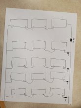
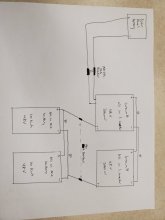
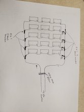
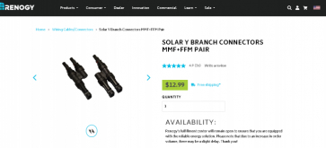
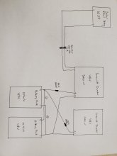
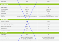
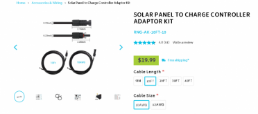
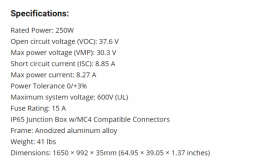
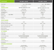
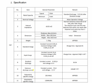
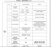
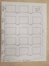
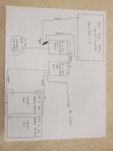
The system: I have 15x 250w solar panels, 2x 48v 10kwh all-in-one battery powerwalls, and 2x 48v 3000w Growatt all-in-one inverters. I have attached the spec sheets below for review. I will be connecting my panels in 3s5p connection for almost 3800 watts total, the battery powerwalls in parallel to give me 20kwh of power storage, and the inverters in parallel to give me a total of 6k watts from my inverters. The best places on my property with the best sun exposure for the panel set up will be between 100-150' from the inverters & battery powerwalls so I'm trying to utilize proper gauge wire to limit loss and guarantee safety. I'm planning on using 6 AWG wiring for my solar panel array since it's rated for up to 55a; I'll be using 4 awg for my inverter and battery powerwall connections. I am planning on inserting a breaker between the solar panel array and the parallel connected inverters as a safety precaution. In an attempt to make it easy and clear, I've attached a couple sketches below to show my plans. All comments, advice, suggestions, and warnings are greatly appreciated but I have a few specific questions:

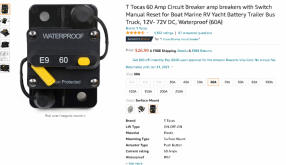
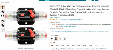
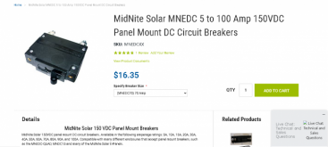
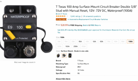
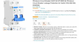
1) Is the attached (picture below) breaker ok for this purpose? if not, what's wrong with it so I can look for a better option? Or do I even need a breaker since my Growatts have built-in protection? I felt redundancy in this case was a good idea since I don't want to burn my house down or damage my system.
2) Do I need to add any additional breaker or fuses between the battery powerwalls and inverter? many of the schematics I've looked at have them but with my powerwalls I believe they have all the necessary protection built-in, but I may be wrong. If I need to add a fuse or breaker here please advise on what I would need.
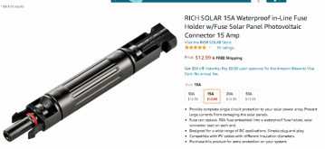
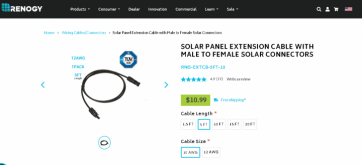
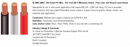
3) Am I good on the 6 awg wire for my panel array? From the calculators and charts I've looked at, if I'm understanding them correctly, I would be running 4-5.5% loss, which I think I'm ok with unless there is a safety issue I'm not aware of yet. From what I understand, going with 4 awg would result in a 2.5-3.5% loss, so not a HUGE difference in the grand scheme of things, at least I don't think. I've found some 6 awg wiring that I'm probably going with and have attached the picture below, is this good or should I look at something different. I wasn't able to find any reasonable price on 4 awg, at least not yet, but if that's what I need to go with I'll do some more digging.
4) with the wiring above, since I want to be able to move my panels from spot to spot on the property and this isn't a year round, out in the weather system, is is ok just to run the cable across the ground? Or do I need to run it through a PVC conduit pipe or even underground?
5) Do I need to incorporate a bare copper ground wire? I don't think I need it but I have seen some people talking about it so just wanted to check. If so where along the line would I connect that?

Well that about wraps it up. I've attached as much info that I can think would be relevant but if you need to know something else to make suggestions pleas just ask. Thank you very, very much! I greatly appreciate any and all help offered.
 

Attachments

  • 6 awg wire.PNG
    6 awg wire.PNG
    126.9 KB · Views: 27
  • Circuit breaker option 1.PNG
    Circuit breaker option 1.PNG
    179.7 KB · Views: 15
  • solar panel spec pic.PNG
    solar panel spec pic.PNG
    152.6 KB · Views: 17
  • Growatt inverter specs.PNG
    Growatt inverter specs.PNG
    220.5 KB · Views: 14
  • battery specs.PNG
    battery specs.PNG
    246.9 KB · Views: 15
  • battery specs2.PNG
    battery specs2.PNG
    231 KB · Views: 18
  • solar panel array sketch.jpg
    solar panel array sketch.jpg
    84.7 KB · Views: 27
  • whole system sketch.jpg
    whole system sketch.jpg
    71.8 KB · Views: 30
I see an AC breaker. Is that what you want to use for the 6 awg wire from PV panels?
An AC breaker will fail to interrupt DC. At full voltage, it would just burn.
You can get DC breakers from Midnight Solar. "Non-polarized" would be best, but polarized can be used in some circumstances.

Your panel array is just PV panels wired together. Need a fuse or breaker for each string of three. Fuses would be good.
Breakers are also sold for that purpose, usually non-polarized. I believe they won't work in that case, but the vendors claim they will.
I suggest a touch-safe fuse holder for each PV string, and a breaker or switch to disconnect the entire string from the charge controller (unless it already has a switch built it.)
 
Hi Hedges, I really appreciate you chiming in. To be honest with you, that being an AC breaker didn't register. I was originally going to go with the breaker attached below but it's only rated to 72volts and with my 3s5p I'll be at 90.9VMP, so I didn't think it would work or be safe so I went with the other one that I saw was rated at 400v, it didn't click that it was ac vs dc. So, thanks for pointing that out, I'll have to dig into some of the options from Midnight Solar as you suggested. As far as the fuses for the strings I didn't know if I needed them or not since It was being wired into an all-in-one inverter that has protection but I did consider it and looked at the fuse below for that purpose. It's a 15a and I'll be at 8.27a per 3 panel string so I think that would suffice, or I could go with a 10a of the same if 15a is overrated. I had also found the mini breakers below but they are only rated to 24v and start at 20a which I thought was under rating on the voltage for my system and over on the amps. I'll definitely look into some other breaker/ fuse options. Other than that does it look ok? Thanks again!
 

Attachments

  • Circuit breaker option 2.PNG
    Circuit breaker option 2.PNG
    184 KB · Views: 7
  • 15A fuse.PNG
    15A fuse.PNG
    169.6 KB · Views: 7
  • mini breaker.PNG
    mini breaker.PNG
    203.4 KB · Views: 7
10A fuse is too small for 8.27A PV - size 1.56x times panel rating (25% over for extra light from nearby clouds, 25% over for headroom). 15A is good.

If the all-in-one has two separate MPPT inputs then no fuses needed (you have only 2 strings parallel), but if 3 strings in parallel then each should be fused.

There are DC breakers which have same appearance as those AC ones. Both Schneider and Outback have them. There are also various switches, but DIN breaker may be most compact and economical.

PV wiring I don't worry about several percent voltage drop, only happens at peak sun, and everything adjusts to work.
For battery we like to go way oversize, help with surge to start loads. Like 2/0 rather than 4 awg, and keep very short.

Your drawing has second battery daisy-chained of the first. That gets extra IR drop.
Best to connect inverter to negative of one battery, positive of other, for perfect symmetry.

You have two, 3000W 48V inverters daisy chained. Wire each of them directly to battery. That gets current down to 65A each wire, and 4 awg is more reasonable.

Entire PV array goes to one inverter.
Put 2 strings to one inverter, one string to the other. Now you don't need fuses per string.

Use at least one battery fuse or breaker, maybe 175A. Or one per inverter, maybe 80A to 100A.
"ANL" is rated either 3000A or 6000A short circuit current interrupting ability. (a car battery can put out 3000A)
"Class T" is rated 20,000A interrupting.
Fuses are supposed to be small enough to protect the wire. 4 awg 90 degree C single conductor in free air is good for 140A.
So one, 100A or 125A fuse per inverter would be good.
 
Hi Hedges,

I appreciate you getting back to me. Unfortunately, you're shooting a little over my head. So let me see if I understand what you're saying. I understand what you're saying about the 15a fuse. But you say that I have 2 strings in parallel. I actually have 5 strings of 3 panels each, hence my 3s5p unless I'm misunderstanding what you're speaking about. So it sounds like you're saying that I need to connect a 15a fuse to each of my 5 strings. For this I'd use the fuse pictured below, in a 15a version. And I assume that I'd connect the fuse to the positive connection of each 3s of the panels? In this set up I would not need a fuse between the series panels, just in the parallel connection, is that correct? Please see my quick sketch of this below as I tried to quick draw what I'm thinking you're explaining.

Based off your advice I've also found the below Midnite 150vdc 70a breaker that I'll use between my solar panel array and the inverters. Please see below to see what I'm looking at and whether that's good for this. I'm at 90.9vmp and 41.35a coming off my panel array so I figure this would be a good option. Would there be any benefit in using this Midnite breaker at a lower 15a rating instead of the 15a fuses that I was originally looking at going with? They are about the same price and if one is better than another then I'd go that direction.

Where you say "Best to connect inverter to negative of one battery, positive of other, for perfect symmetry." I was planning on connecting the batteries and inverters in parallel, that's my understanding of what I need to do to maintain 48v. With your advise, are you saying to stay with a parallel connection on both but connect each inverter to the battery bank? ie the positive battery side to one inverter and the negative to the other like my picture below? I would probably still step into 2 awg wiring for both the battery to battery parallel connection, the inverter to battery connection, and the inverter to inverter parallel connection as you say to offer more safety.

Please let me know if I'm pulling together what you're saying correctly or if I'm way off again. I'm sorry to sound so dumb and I appreciate your patience and time. Thanks.
 

Attachments

  • 15A fuse.PNG
    15A fuse.PNG
    169.6 KB · Views: 9
  • revised panel array w fuses.jpg
    revised panel array w fuses.jpg
    83.1 KB · Views: 13
  • midnite solar 150vdc breaker.PNG
    midnite solar 150vdc breaker.PNG
    133 KB · Views: 13
  • Revised solar sketch.jpg
    Revised solar sketch.jpg
    65.5 KB · Views: 15
The 15A fuse and fuse holder looks good.

Location of fuses in PV array looks good.
To connect as shown you would probably have to cut and splice wires.
You can get "Y" or other connectors, but they would need to be large enough wire gauge to handle the current, which is 5 panels in parallel in some places.

The breaker should work, but it has bolts on the bottom. You may find a breaker with screw terminals to hold wires better than exposed terminals. Perhaps they will be DIN mount

The system drawing has at least one problem.
Battery positive is shown going to only one inverter. Battery negative to only one inverter.
(But connecting the wires to opposite corners of the battery bank like you've done is what I meant.)
1) Use breaker/fuse only in the positive wire, not the negative.
2) Connect negative wire to the inverter which gets positive wire.
3) Duplicate those connections (fused positive, unfused negative wire) for second inverter

I don't know what he wires connecting top of the inverters are for.

Right now, you have all PV panels as one array connected to one inverter only.
Both inverters have PV inputs. I think they each have two MPPT inputs if I remember correctly.
Connect 3 PV panel strings to one inverter, 2 PV panel strings to the other inverter.
If inverters have two separate MPPT inputs, put one or two PV panel strings on each.
No fuses required for PV panels if only 1 or 2 panel strings connected to a single MPPT input.
 
Hey Hedges,

I've been doing some more research on the fuse vs breakers. I also like the extra flexibility of a breaker vs a fuse however with my panels being mounted so far away from my inverters and battery packs, around 100-150ft, I would have to mount a panel box to the end of my panel racking system to run each of my strings to, and then run my 4 or 6 awg wiring from there to my inverters in the garage. It seems that would raise my costs quite a bit and it seems so much simpler to just utilize the inline fuses. So, taking that into account, I'm leaning toward running my 3 series strings in parallel using the Rich Solar (or Renogy) 15a inline fuses below connected together with a 2-to-1 y branch connector which is rated at 50a and then run them all into the Midnite breaker before my inverters which I'll mount the breaker in a box since it looks like from the pictures it's a front mount breaker. I looked at some other breaker options and did find the other 80a one pictured below but don't know if that's any better, looks about the same to me. I will use the 5' or 10' 10 awg extension cables between the strings as needed to connect them since the cables on the panels won't be long enough to reach all the way across all 5 strings. Then into the last y connection I'll lock in my 6 awg wiring to run from the panel array to my inverters in the garage. How does that look???


So I understand what you said about only 1 fuse on the positive wire and eliminated it off the negative wire. However, I'm a little confused about what you're saying about the inverter to battery connections. 2 posts ago you said
"Your drawing has second battery daisy-chained of the first. That gets extra IR drop.
Best to connect inverter to negative of one battery, positive of other, for perfect symmetry."

So when I redid my sketch I attached the batteries in parallel connection and the positive from one battery to one inverter and the negative to the other inverter since I have 2 inverters connected in parallel as well. That's what I was showing in my new picture I attached. Are you saying instead of connecting all my solar panels into one 3s5p array and running them into the inverters connected together you think I should run them separate, with 2 strings attached to 1 inverter and the other 3 strings to the other inverter? Firstly I didn't know I could connect 2 different inverters into the same battery. Secondly, if I do that then I will have 2 inverters I can pull power off of but It will only be at 3000w and not 6000w. Also, and more importantly, wouldn't this require much more 6 awg wiring since I'll have to run 2 of the strings in on 1 run of wiring and then run the other 3 strings in on a separate run of wiring since they are being connected to different inverters. My panels are going to be over 100' away from the inverter/ battery set up so it's going to require a lot of 6 awg wiring. I guess I could just eliminate 1 inverter and run all the solar panels into 1 inverter and just the 1 inverter into the battery bank but since I had 2 of the inverters I was trying to connect them in parallel to boost it to a 6000w system, just in case I needed the extra capacity. Ideally I'd like to keep the panels running together in 1 array, even with it requiring fuses to do so, and then hook that into my 2 inverters in parallel and the 2 battery packs in parallel, unless there is some reason not to do it this way. According to my inverters they can be connected up to 6 inverters in parallel. Please clarify this for me, sorry to be dense. I have drawn a new sketch based off of what I read you're saying of connecting the batteries to one inverter and then connecting them to the second but it doesn't seem right and I don't see how to connect the inverters in parallel to get my 6kw in this fashion.

Thanks.
 

Attachments

  • 15A fuse.PNG
    15A fuse.PNG
    169.6 KB · Views: 8
  • revised panel array sketch 2.jpg
    revised panel array sketch 2.jpg
    65.4 KB · Views: 8
  • renogy solar panel extension cable.PNG
    renogy solar panel extension cable.PNG
    109.2 KB · Views: 9
  • renogy solar y branch panel connectors.PNG
    renogy solar y branch panel connectors.PNG
    50.6 KB · Views: 7
  • Midnight 150vdc 80a breaker.PNG
    Midnight 150vdc 80a breaker.PNG
    126.6 KB · Views: 9
  • new sysetem suggestion sketch.jpg
    new sysetem suggestion sketch.jpg
    49.4 KB · Views: 10
MNEPV 80A is polarized, I think that is OK as a disconnect between combined PV array and inverter/charger. It would not be good between inverter/charger and battery because current flow there is bidirectional.

Your new drawing of two inverters, each with its own wires to the battery bank (consisting of two 48V batteries in parallel) looks good.
Inverter cables go to positive terminal of one battery, negative terminal of other, which will balance current draw equally.

The way you drew PV array, with "Y" branches and fuses, works so long as the wires and connectors carrying combined current can handle it. MC4 only comes so large, but if 8 awg rated 50A is available then OK.

I used a small waterproof electrical outlet box with wire nuts inside to join multiple panel strings, then ran stranded wire in conduit.

You have two inverters drawing from the shared battery (You did in earlier drawing as well, but only had one wire connected, needed two). Assuming that is allowed (I haven't read your manual in detail), don't see any reason why each couldn't have PV panels attached as well. So you should be be able to split the array across the two inverter/chargers.

If you wire two PV strings to one inverter and two to the other inverter, smaller wire gauge can be used, won't have to be 6 awg.
Making both pairs of wires large enough for 3 strings would let you add a string later.
Does the inverter/charger have only one MPPT input, or two? If two, you could pull wires for each MPPT input, 4 pairs total. With one or two strings per MPPT, no fuses needed. You could expand to 8 strings later. Smaller gauge wire is easier to pull, too.

Each inverter/charger will have a maximum PV power it can support, and a maximum AC output it can generate. It will draw from battery as needed. You should be able to run both at full load and accept full charging from each if battery can handle the current.

Since the inverters can be paralleled, their AC output will add together. Their battery charging and discharging current will be added together.
Are they 120/240V split phase? The manual probably just shows all AC hot, neutral, ground wires tied together. Or maybe combining at a breaker panel, with a breaker for the hot wires L1 and L2. My Sunny Island is like that, but 120V only. I have four, connected series/parallel through breakers for 120/240V output.
 
Hello Hedges, and once again thanks for the help. I hope you and your family had a great and safe Christmas and New Year. I'm hoping 2021 is better than 2020 but I'm ready to finish this project up just in case it's not, lol.

I understand the MNEPV is good for the protection between the PV array and the Inverters but not between the other components because the current will be going back and forth between the inverters and batteries. So, I will consider using the other breaker attached below for the connection between the batteries and inverters. It is bidirectional, 100A, and listed good for 48 v so I think that may work between the inverters and batteries, is that a better option?

Probably a very stupid question in regards to the Y branch connections. I know the panels have the connections already mounted on the panel, so the 2 in ports will just accept the cable coming off each string of panels and have a 15a inline fuse on the positive ends where needed. The outgoing from the Y Branch will connect into the 4' extension cables which will link strings 1-4. That's easy, my question is when I come to the last Y branch connection coming off string 5, how do I connect it to my 6awg wire to run from the panel array to the breaker/ inverters? I'm assuming I need some kind of adapter to connect the 6awg into that will allow it to clip into the Y branch connector's out but I don't know what it's called and can't find anything on the websites I'm looking at.

I like your idea of running the array into 2 separate lines, one with 2 strings and one with 3 strings, connected into the different inverters. I would be interested in this idea to reduce the stress on the system and to provide more safety with less chance of fire. Would there be any problems with the batteries charging unevenly since one inverter would have 6 panels (3s2p) coming into it and the other would have 9 panels (3s3p) coming into it? I don't think this would save me any money, and it may cost more, since I'll have to buy twice as much wiring, lower gauge yes but 2 runs of wiring. With my array being 100-150 feet away from the inverters and batteries, instead of buying 300 feet (150' positive + 150' negative) of 6awg wiring I'll have to buy 600 feet of 8/10awg. I have been leaning toward keeping the system as a 3s5p inputting into 1 Inverter because I thought it would be easier, with less wiring to run. I was playing with the idea of having 2 separate systems and not connect the batteries or inverters together which would offer a few benefits such as redundancy if something happens to one inverter/ battery/ array it doesn't kill my whole system and I have a back up, less need for fuses/ breakers, and lower gauge wiring being needed. However, I felt it easier to connect it all in one system with less wiring being required and I get a higher maximum output from my inverters, 6000w instead of 3000w. I believe each inverter only has 1 MPPT but I'll have to double check on that. My Growatt inverters are 120v split phase as shown below.

While I'm learning so much with this and you've been a huge help, the more I learn and the farther I get the more worried I get, lol. I'm thinking that maybe I need to find at least a consultant if not a full electrician, even if it costs me a little money, but I don't know how much this would cost or where to find a KNOWLEDGEABLE and RELIABLE consultant. I'm pretty smart, can draw out a plan, and execute the plan but for some reason I'm struggling with this electrical stuff more than I usually do with my projects. This past year I built a large raised bed garden, a storage shed, a very large chicken coop with fenced in run, and a 20x20 greenhouse. I didn't imagine this solar project would cause me so many problems but none of those other projects involved electricity, lol, and this is much more dangerous. I think, with your help, I've come up with a good overall plan and understand it, but if I could get someone to walk through it with me verbally it would make me much more confident and comfortable. Do you think that would be a good way to go? And if so do you know if anyone on this site or online that offers that kind of service that really is a pro with this stuff?

Once again, thanks for the help and your time!!
 

Attachments

  • Amazon 100a fuse.PNG
    Amazon 100a fuse.PNG
    209.9 KB · Views: 4
  • Growatt info.PNG
    Growatt info.PNG
    209.4 KB · Views: 5
So after I posted I was thinking about this adaptor kit that I found on the Renogy Site and it dawned on me. If I got the 10awg kit in 10' length then I could run that from the out of the Y branch connector on the final string into my breaker since on the other end it's bare wire. Then come out of that breaker with my 6awg wiring. Would this work ok, is it ok to go into the breaker with 10awg and out with 6awg? Would the 10awg wiring be ok for that short of a distance? From the calculator I looked at it looked good if I'm looking at it right.
 

Attachments

  • Panel to Controller adaptor kit.PNG
    Panel to Controller adaptor kit.PNG
    87.1 KB · Views: 6
If authentic not counterfeit such a breaker might be OK. There are bad look-alikes.
It probably doesn't have very high interrupt rating in case there is a dead short; the battery can deliver a lot of current.

Midnight has non-polarized breakers with quite high ratings:


Two inverters both charging two batteries connected in parallel, even with uneven distribution of PV panels between batteries should still keep charging of batteries balanced.
Lower current through an inverter or charge controller tends to be more efficient and longer lived, since heating of transistors goes as the square of the current.

For connecting the smaller gauge MC cables to larger wires, use a combiner box or other suitable enclosure, water tight if outside. I use junction boxes with glands where cables enter, and conduit carrying home run wires. If you're using 6 awg obviously enough panels in parallel to need fuses. But I think you have enough MPPT inputs between the two inverters you could have just two strings in parallel on each, no requirement for breakers or large cables. I would either join two strings in parallel and run one pair, or run each pair with its own 12 awg wires. That is what I've done for the most part.


There may be forum members near you who can provide assistance.

I understand SolarQueen does PV system design; her employer AltE Store also sells components. For a small fee she also creates full drawings. Someone like that documenting the connections, wire sizes, breaker ratings could help you.

When it comes to actually bolting cables to batteries, connecting inverters, connecting PV panels, it is important to avoid shorting things out, wiring for too high voltage, connecting backwards. Those mistakes could cause injury or damage. Practices like using insulated tools for battery connections and measuring voltages before making connections can help avoid that. Given the cost and risk, you might want help from someone familiar with PV and battery (not just your typical electrician)
 
Back
Top