so back to the original problem.
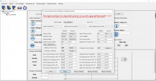
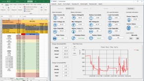
Here I am again. After rewiring my charge controller last night, and having it completely disconnected for hours, I would have thought that the most recent set of configuration adjustments would be honored today. I deferred reconnecting the optional load and kept the use down to minimal in an effort to push the voltage back up to max and check the fully charged voltage settings. Again, my settings are disregarded in favor of who knows what. I'm well past my current max boost voltage of 54.4v and now past the last max boost voltage of 55v with a solid, steady 2,200w+ flowing in. I don't understand what it's shooting for. Before I rewired, I felt like i was closing in on how this thing works, but i'm back to scratching my head as the theories that seemed to be firming up have now been decimated. It's really a mystery how this thing works. I've been above boost voltage for hours so the boost duration also seems useless. It's frustrating...