I know others have said they have done it repeatedly, but I would be at least a little concerned about the affect on your fridge's compressor motor by fast-switching out-of-phase.
The transfer from a dead (or nearly dead) utility to solar inverter isn't much of a concern. Switching from inverter to a live utiltiy is the trouble-area, but only if the fridge happens to be running while the transfer occurs. Fridges cycle on an off, so the concern is limited to those times that a transfer occurs while the compressor is actually running.
While running, statistically, about a 1/4 of the time, the wave forms will match up reaonsably close... not really any concerns. About 1/4 of the time, you'll get a nearly 180-degree out-of-phase transfer, i.e. 240v volts (2x120V)... concerning. About half the time, you'll get this gray zone of 45-135 degree leading/lagging switch which could also be a concern. When switched out-of-phase or unsynchronized, motors will quickly adjust to line up with the new magnetic fields via some pretty large motor surge currents, similar to motor starting from rest. This stresses the motor windings and all the mechanical equipment connected to the motor shaft.
When transfers occur, sometimes you'll be lucky. Sometimes the waves will be 180-degrees out of phase and you'll have higher surge currents. You may experience occasional breaker tripping over the course of time. As more transfers happen, shortened life of your fridge motor may also come into play. But since fridges don't run all the time, its more of a roll of the dice on how lucky or unlucky you are. Odds, however, are in your favor, but bad things can happen.
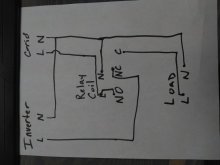
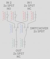
If you're already handy with schematic wiring diagrams and custom control circuits, you might consider going the route of two power relays (normally-open contacts) with minimum of 125VAC contact ratings and a control timer with N.O. and N.C contacts that drive each power relay to make sure there's a time delay when switching from solar to utitily. There might be a way to do something with a current-switch and only one power relay, but I haven't thought through that completly. Yes there would be extra cost, but also reduced worry.
Some may say that's overkill, but that's how I would do it.