diy solar

diy solar

JiKong (JK) (Neey/Hankzor/HelTec/etc) Smart BMS with Active Balancer BT/Can/RS485 (Input Discussion pre-purchase)

Anyone have experience with the JK-B2A25S60P ?
Need the high peak current capability of a relay BMS, planning to charge and discharge a 16S LF280K pack several times a day with fairly high charge rates with my Quattro 48/140/10000VA. Due to the size of the charger/inverter, i need a precharge. Due to the high charge/discharge rates i think i need a active balancer.
This unit seems to tick all the boxes. From what i can see it has precharge, external relay support and a serial interface and driver for the Victron GX system ?
I do however have a couple of questions, are the relay/contactor outputs all fixed 12 V ? Based on the limited amount of documentation it seems like it ? If this is the case, this is an advantage as it seems like it is much cheaper/easier to get hold of EV200 with 12 V coil than 48 V coil. At least for the cheap ones on AliExpress (clones?).
Anyone know if the Venus serial driver is compatible with the JK-B2A25A60P or just the cheaper ones with internal switch ?

Perhaps the biggest question is with the precharge output, it say in the manual that this can be used for 12 V buzzer or precharge relay. I do not however find anywhere in the documentation where it say how to enable the precharge/buzzer ? Another question is what how long the precharge is in for and how long the delay between the precharge engangement and the main contator engagement ?
Another one is if the precharge output is capable of driving a large EV200 relay directly or if i only can use smaller mosfets or similar with this output.

Anyone that have any knowledge on this unit ? It does seem to be the swiss army knife that can do everything. It is the only BMS with relay and active balancing that i have found.
I don't know the answer to other questions, but I wouldn't use an EV200 relay for the pre-charge circuit anyway. I'd limit the pre-charge with a suitable resistor and use a much cheaper relay in the pre-charge circuit.
 
I agree that it is completely unnecessary. I have some small 30 A SSRs i could use instead for this that i might use instead. The clone EV200's are however so cheap now that the price difference is not that big :O

With less than two watts of holding current on these as well, it seems like a no brainer compared to having 10-50 cheap mosfets in parallel like in most of the non relay based BMS systems. I would expect both internal resistance and reliability will be better on a mechanical contactor. Especially as long as you configure the inverter/charger to start/stop the charge/discharge.
 
Last edited:
Hi, can someone please confirm the latest 200a continuous model number? I’m getting mixed info from some suppliers. I’m looking for the latest model with ‘can’port and that can connect to the JK touch screen. I’m lead to believe the model is B2a24s20p-can however one supplier advised it’s B2a24s20p and another B2a20s20p. A little confusing

I’m running 2 x 230ah 48v packs.

Cheers
 
I have a question about inverters connected to the JK BMS. If the JK shuts down for over or under voltage what happens with the inverter. Will there be a current spike when it comes back on?
 
I have a question about inverters connected to the JK BMS. If the JK shuts down for over or under voltage what happens with the inverter. Will there be a current spike when it comes back on?

Overvoltage no, since it keeps discharge enabled, only charging is being disabled. This makes sense because you really want to keep discharge enabled on an overvoltage condition to bleed off the cells.

On low cell voltage, yes - but the inverter will also try to run from the solar charge controller once sun is available and it tries to charge the battery. Ideally you want to have a mechanism to either 1) keep the inverter off in this situation or 2) have an automatic pre-charge system in place with inverter on/off function. I'm not sure any of these solutions exist off the shelf...
 
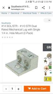
Any thoughts on using this to connect the 2 battery negative leads? Bolt directly onto 6mm stud in my case? Just brainstorming and came upon this.
 

Attachments

  • Screenshot_20220314-125548_Chrome.jpg
    Screenshot_20220314-125548_Chrome.jpg
    185.5 KB · Views: 41
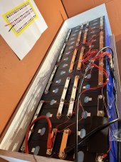
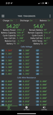
Im using this but it hasnt arrived yet so I just soldered the 4awg to the 2x7awg lines:

Im using 32pcs 280ah
 

Attachments

  • 9540CDF0-BCB7-44A5-BA09-6383EB2C1769.png
    9540CDF0-BCB7-44A5-BA09-6383EB2C1769.png
    932.3 KB · Views: 100
  • 07A3B9B6-2B5C-4ED7-BF11-56B71D696282.jpeg
    07A3B9B6-2B5C-4ED7-BF11-56B71D696282.jpeg
    207.2 KB · Views: 104
  • 984EE3B2-03FA-461E-8DEB-882FAE69E38D.png
    984EE3B2-03FA-461E-8DEB-882FAE69E38D.png
    875.4 KB · Views: 100
I've been trying the last week to find a source, any source for this JKBMS 2A24S unit. Everything I see has a one month wait to come from overseas. Anybody got one they want to sell ? Or know of one stateside. Florida is my locale.
 
Thinking out of the box today. Since I cannot get my jkbms anytime soon. Is it safe to say that if 17 cells are near totally charged. aka 3.4 volts on each one. That using them and avoiding the extreme ends of the charge/discharge range, I am rather safe ? Meaning this only damage to occur is to the first cell to discharge below 2.0 volts or on the charge end the first cell to go above 3.65 volts ? So if I limit myself to the 'inner' 60% I am rather safe. Do not go below 20% or above 80%. Thoughts ?
 
280ah
So in-turn I can map the cell voltage defined at 20% >> 3.2 volts and 80% >> 3.33 volts.
Keep the inverter range to 17 times that. Discharge Cut Off at 54.4 volts and charge max to 56.61 volts
 
So in-turn I can map the cell voltage defined at 20% >> 3.2 volts and 80% >> 3.33 volts.
Keep the inverter range to 17 times that. Discharge Cut Off at 54.4 volts and charge max to 56.61 volts

No, don't do it. Be patient. The BMS monitors individual cells, your charge controller/inverter does not. Don't assume 3.4V means anything. Don't assume any voltage means anything with LiFePO4.
 
Thinking out of the box today. Since I cannot get my jkbms anytime soon. Is it safe to say that if 17 cells are near totally charged. aka 3.4 volts on each one. That using them and avoiding the extreme ends of the charge/discharge range, I am rather safe ? Meaning this only damage to occur is to the first cell to discharge below 2.0 volts or on the charge end the first cell to go above 3.65 volts ? So if I limit myself to the 'inner' 60% I am rather safe. Do not go below 20% or above 80%. Thoughts ?
If it all works out nice no problem. If it does not, $$$. You money, your choice.
Do you feel lucky?
 
Hello
I got mine a week or so ago.
The actual bms is very nice and working good.
I also bought the can bus module hoping to get it to communicate with my victron cerbo, that failed big time.
Doing a little research, i dont believe its true canbus??
I can confirm that it is transmitted something as my cerbo gx is receiving something
See pic
Hello,

Did you take a look a this driver for Victron ?


It looks like working fine with JK bms
 
Good Day folks,

I am now very seriously looking at these JK BMS' (common rebrands in title) after watching several review vids (Good Job Andy BTW) and doing my own digging into them.
Ref to Andy's 1st vid that caught my eye on these.
Can't help but love the Exhuberance.

Small backstory:
I have several LFP battery Packs both production (main bank) and a few "Utility" packs, all LFP of course. As I built these over a period of time, things got somewhat muddled because of different versions or different pieces... IE 5 production packs are Chargery 300A BMS' & QNBBM-8S Active Balancers and utility packs JK & JBD BMS' with HelTec Capacitive Active Balancers... Quite the Kerfuffle indeed. I've decided to tackle this calamitous compilation of components and finally get it all sorted and aligned to completely finalize my systems. There will be a sale on a LOT of stuff, as it's also time to "clean up & clear out", will be posted later.

I am going to align everything identically, production & utility packs included. I intend to place the order this coming Monday (Nov.29) so any feedback from people actually using this gear is most welcome. Below is precisely what I am looking at.

JK-BMS [24S 2A 150A BT] with BlueTooth Part Number: B2A24S15P $143.29 USD
Product Link: https://www.aliexpress.com/item/1005003104573871.html
plus CANbus Module + RS485 Module $7.73 USD each Comms access besides BT is required and future-proofing as well.
Product Link: https://www.aliexpress.com/item/1005003451100409.html
** Possibly adding [LCD for 60P] display module but not sure ATM. Actual User Feedback would be helpful. they are an extra $30 USD ea. Not for these models, only 60P.

NOTE ON WIRE SIZE: The B & C wires are 7AWG Silicon capable of 200A, the sense/balance leads are 7awg per HankZor client services.

JiKong-Lithium battery smart bms instructions.pdf (Nov.23.2021)


Table of models/versions. (thumbnail, click to expand)
View attachment 73679
Thanks in Advance for all Feedback & Info.
Steve
Calamitous compilation of components! Love it!
 
I started as a Board Level Eng at Control Data Corp Long ago then flipped to SW when the frames went away.. I ended up a CBE, ECNE, MSCE and was a Core Engineer for DND after having worked for IBM, MS and a few other miscreants. I have Node-Red on Raspi talking to the Classic and the Samlex EVO (NDA - can't discuss that) and wanted to get the Chargery's in that but gave up on that... Once I put the new setup together and "common" I'll lay with the software and see where it ends up BUT it isn't a priority.
Wow. I have not heard the name "Control Data" in many years. I actually graduated from the "Control Data Institute" they had in Manhattan a long time ago. I think the Cyber 80 was their newest machine back then. I dont remember if it was Octal or Hexidecimal based. That school was also one of the first computer based, self paced, online training in the classroom instruction.
I ended up at Digital Equipment Corp. After that school. Sounds like we have similar backgrounds, but I stayed on the hardware side, passing through Digital, Sun Microsystems, Compaq, HP, Hitachi Data Systems, EMC, and Dell. I was also an MCSE and did a stint as an MCT for a bit. I wonder if we ever crossed paths.
 
Control Data Institute was one of their teaching enterprises back in the day... 8" Floppies LOL ! I have familiarity with that tech. I actually worked on their Frames at CanadaPost which also had a fleet of IBM-3090 Series and even a dusty & crusty Amdahl machine back them... I jumped from Hardware to Software - Network Engineering that took me into defence & other systems. I was also on the Protocol Standards & Communications board for a bit. We may have crossed paths but that is a lifetime away now for me. I do NOT miss the stress & BS that went with it !
 
Control Data Institute was one of their teaching enterprises back in the day... 8" Floppies LOL ! I have familiarity with that tech. I actually worked on their Frames at CanadaPost which also had a fleet of IBM-3090 Series and even a dusty & crusty Amdahl machine back them... I jumped from Hardware to Software - Network Engineering that took me into defence & other systems. I was also on the Protocol Standards & Communications board for a bit. We may have crossed paths but that is a lifetime away now for me. I do NOT miss the stress & BS that went with it !
Yeah, 8" floppies were interesting. I started just when card readers and paper tape were being phased out. The US Merchant Marine Academy had a very cool realistic bridge simulation that ran on a Digital PDP 11 with the program loaded from paper tape. That was when programming was done in machine language, and everything could run from less than 1MB of memory.
One of the first video games I ever played was called Lunar Lander, which ran from one of those 8" floppies on a PDP11.
It used realistic physics for the lander on the moon. If you landed properly, the little astronaut would climb down from the LEM, and walk over to McDonalds on the moon to order a burger and fries?.
 
Control Data Institute was one of their teaching enterprises back in the day... 8" Floppies LOL ! I have familiarity with that tech. I actually worked on their Frames at CanadaPost which also had a fleet of IBM-3090 Series and even a dusty & crusty Amdahl machine back them... I jumped from Hardware to Software - Network Engineering that took me into defence & other systems. I was also on the Protocol Standards & Communications board for a bit. We may have crossed paths but that is a lifetime away now for me. I do NOT miss the stress & BS that went with it !
Protocol and standards? So you were part of IEEE? I assume IP protocol? Thats a real deep dive into the bits buddy. God bless, you must be wicked smart.
 
https://www.jkbms.com/contact/
Unfortunately
This is not the official website of jkbms
You can view the logo shape on jkbms and the logo shape on the website. They are different,
funny to click on the alibaba or aliexpress shop that are mentioned or linked there
on Aliexpress you will land in the ENJ Battery Store which is empty
on Alibaba you will land in the E+J TechnologyGroup Store which is empty too

This one seems to be the real JiKong BMS Site I guess, but pretty slow.
 
Can anyone here manage to submit a support request at JK BMS site ?

www.jkbms.com

www.jkbms.com

The hour clock just circles forever.
 
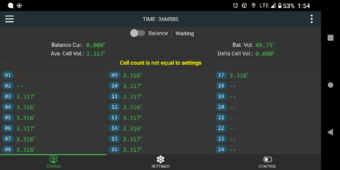
I have bought 5 of these JK-B2A24S active balancers over the past 3 years. JKBMS. Rather happy until one just broke itself.
It shows me '--' for the cell voltage on cell 1 and cell 2, the rest are all fine.
This condition triggers the CELL COUNT IS NOT EQUAL message and so the balancer has disabled itself.
There is no way to workaround 0.00 at cell 1 or 2.
There are correct voltage right down the pins on the module, cells are fine, just erroneous sample inside black module.
When I fetch data on bluetooth it shows all good except 1 and 2.

JK bad --
Fri, 08 Mar 2024 04:58:25 DEBUG JKBMS tot=49.87v low=0.0v high=3.326v delta=3.326v soc=None%
c1=0.0v c2=0.0v c3=3.325v c4=3.323v c5=3.323v c6=3.325v c7=3.325v c8=3.323v c9=3.325v
c10=3.325v c11=3.325v c12=3.325v c13=3.326v c14=3.325v c15=3.325v c16=3.325v c17=3.322v

below is when all was good ---
Wed, 29 Nov 2023 04:39:24 DEBUG JKBMS tot=56.78v low=3.336v high=3.348v delta=0.012v soc=85%
c1=3.348v c2=3.348v c3=3.347v c4=3.344v c5=3.338v c6=3.337v c7=3.338v c8=3.336v c9=3.338v
c10=3.338v c11=3.337v c12=3.336v c13=3.338v c14=3.338v c15=3.337v c16=3.337v c17=3.338v

Cannot find any way to get help or service.
It seems a firmware revision could allow this type of failure to workaround and use cells 3 and up in the process.

And yes my system has always had 17 cells in the bank.
 

Attachments

  • Screenshot_20240311-135415_极空BMS -- and --.png
    Screenshot_20240311-135415_极空BMS -- and --.png
    288.7 KB · Views: 0
Last edited:

diy solar

diy solar
Back
Top