diy solar

diy solar

Fine Art of wiring small MCB Box

burgerking

New Member
Joined
Apr 6, 2022
Messages
368
Location
Subic, Philippines
I currently have these IP65 8P plastic MCB box.
It is the most available MCB box locally and getting a bigger box from China will take weeks.
1656025033789.png
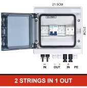
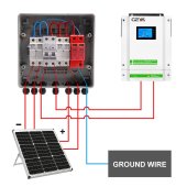
I intend to turn this into a 2 String PV disconnect + Surge Protector to be installed near the Inverter.
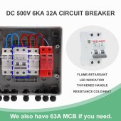
I will be adding 2 pairs of SPDs and 2 pairs of DC Breakers (or Fuses).
There is hardly 3 cm of space at the top and bottom of the MCB to route wires around.

METHOD1:
I drill 8 4mm holes, and match the location of these holes with the MCB ports such that I don't have to route the wires on the inside but from the outside.
I can add rubber silicon grommet to add a little water seal. Or dab of silicon sealants...
1656026135374.png

METHOD2:
Or I install PG7 Cable Glands or MC4 connectors at the bottom.
Match the location of these Glands to the MCB ports.

METHOD3:
Or simply install larger PG13.5 cable glands under each MCB/Fuse.
Two wires passes through each Cable Gland. it is thus far the EASIEST method.


On another BOX for AC disconnect, I tried Method2... Too much work IMO.
There has got to be a simpler solution.
 
I have the same boxes. They are tight but they fit my needs. I would recommend anything that provides strain relief. The terminals shouldn't be the support for the conductor.
 
I'm placing mine directly beneath each inverter.
With the AC input and output breakers, battery breaker, solar breaker and SPD, and pre charge resistor button. (That's a tight fit)
 
I have the same boxes. They are tight but they fit my needs. I would recommend anything that provides strain relief. The terminals shouldn't be the support for the conductor.
CASE1 is out then.

I'm placing mine directly beneath each inverter.
With the AC input and output breakers, battery breaker, solar breaker and SPD, and pre charge resistor button. (That's a tight fit)
I'd appreciate if you can post photo of that setup.
I plan to add more inverters in the future
 
Not installed yet, this is for the version two of my setup. When completed, there will be pictures.
But, it's going to be a while. I have some other remodeling to do first. All I have currently is a pile of parts and a sketch.
 
I did both over time. Route solar cable through small drilled hole in the box, OR use the knockouts and clamp MC4 plugs there that connect to the modules inside via short pigtail. The later one is far harder to do because these boxes are tight.

Note that you should run PV DC over a breaker first then to the SPD! Imo you should be also fine with a normal AC breaker because normally you will not switch it off when any current is ever flowing through the SPDs. If there is some overvoltage you actually do not want the breaker to trip until the SPD absorbed the spike. So you should use D curve breaker...

ps the breaker is there so you can switch the SPD without killing yourself
 
You should never put an AC breaker on a DC circuit.
If that breaker trips for any reason, while current is flowing. It will more than likely catch fire.
 
You should never put an AC breaker on a DC circuit.
If that breaker trips for any reason, while current is flowing. It will more than likely catch fire.
there is no situation where this breaker should trip with current flowing. It should NOT trip
 
Shouldn't doesn't mean won't.
There are a lot of things that Shouldn't happen, that do happen.
 
Shouldn't doesn't mean won't.
There are a lot of things that Shouldn't happen, that do happen.
you do not understand SPDs and voltage spikes... there is no current via the spd! and breaker should NOT trip while current is flowing. Even if it trips the spike is over in some miliseconds! So nothing will burn or arc because there will be NO current you understand?
 
If the only thing connected to the breaker is the SPD, then there's no reason for the breaker. If anything, it could stop the SPD from doing its job.
But, it's your system. Do whatever you want.
 
If the only thing connected to the breaker is the SPD, then there's no reason for the breaker. If anything, it could stop the SPD from doing its job.
But, it's your system. Do whatever you want.
the purpose of the breaker is to allow you to change the SPD modules if they stop working without danger for your fingers...
 
the breaker should NOT trip, or it will interfere with the proper function of the SPD. equally you can just put a disconnect there.
 
If you're going to turn off the circuit before you turn off this breaker. This breaker is pointless in my opinion.
 
AC vs DC breakers.
Last week, my 20+ year old main disconnect 100A Square D breaker broke.
And since I do not have any spare high current breaker around, I was forced to use a 32A DC Breaker...
No explosion, no burning... no idea at what current it will trip...

Yesterday, replacements arrived.
I replaced 3 breakers in that gutter box.

I dare not use AC breakers on high voltage DC though...
 
you should use DC breaker where ever you have one, to be code compliant. still this breaker will and should never trip! It should not trip on a spike because it would make the SPD pointless. It will not trip on any short circuit because your solar array will likely never have the amperage to trip it (e.g. you have a lightning nearby that burns your wires at night, there is no solar power...).

Most SPD manufacturers specify you do not need a breaker. these devices break open on damage. Breakers are actually to protect the wiring to the SPD, not the SPD.
 
hmm...
 

Attachments

  • S5d1594c286884c98bfb01ff44f80651cE.jpg
    S5d1594c286884c98bfb01ff44f80651cE.jpg
    278.1 KB · Views: 20
  • ngntyjt.jpg
    ngntyjt.jpg
    190.2 KB · Views: 23
  • fsdfsf.jpg
    fsdfsf.jpg
    154.9 KB · Views: 23
This is nice box. Much taller by 6cm than the ones I use. It has ample space to route wires around.
I wanted this but there is no local supplier.


1656193682570.png
Notice there are 7 Ports at the bottom. NICE!

PS. I actually have 1 of this; it came with the Growatt bundle I got from a Chinese supplier.
And in said box, was 2 DC MCBs, 1 SPD and 1 AC MCB, with 1 big PG25 for all the wires - face palm!
 
Last edited:
I'm sure that it costs more than it's worth to me.
But if it fits your needs and budget, go for it.
 
I am using Deye inverter, and it has 2 AC connections. Since I only need 2 Breakers for the AC side, I initially thought of using a 5P Box:
1656194775728.png

However this box leaves no more space for expansion such as SPD for instance. So I went and use an 8P box:

1656194745545.png
I ended up using 2 PG16 Cable Glands: one for GRID side, and another for the Inverter Side. (Above is a used box I now use for simulation. note there are holes top and bottom of box - a big newbie mistake....)

THHN #6 sure is stubborn and I had a hard time playing with this config. Using a mock up box helped: I get to experience and figure out how each individual components interact with each other. Drawing the wires on paper is easy; but physically wiring them is a big chore!

LESSONS I learned:
#1. Do not put holes on top of the box. It will make it leak water. Dont rely on Cable Gland to seal the water (from the top) it will eventually leak.
#2. Cable Gland is your friend. But dont get too cocky drilling individual Cable Glands for each wire. It is too much work not worth DYIing it. In my experience, group wires together into a single cable gland; this lessens the task a lot.
#3. Get the bigger box as posted by SunsetSolar. Bigger box is much better. You can even run fat wires behind the MCBs.
#4. Thick fat wires is a different story. Most of the drawing plans on paper are not feasible with thick fat wires. Use softer wires. Silicone? BVR?
 

diy solar

diy solar
Back
Top