diy solar

diy solar

Victron VenusOS driver for serial connected BMS - JBD / Daly / ANT / JKBMS / Heltec / Renogy / Tian / ECS

Hi @Louisvdw,
1. I currently use a JKBMS and I cannot get the BMS to display on my device list.

2. I installed the driver on my Cerbo GX but enabling the driver shows the following:1658762047881.png

3. Checking if the connection is picked up by serial-starter shows the below repetitively:
1658762218579.png

Please help
 
But nothing, even the logfiles are looking worse
@Hubba your battery driver is being started on ttyUSB1 and you are reading the log file under ttyUSB0. That is why it cannot find the log file. Just ready the matching path and see what it says.

Please help
The driver is installed and is being started. Just check the log file for ttyUSB1 to see what is happening (see troubleshooting section on the wiki how to do that)
 
Last edited:
No step further so far. "object has no attribute 'min_battery_voltage' " still persisting. Is there anything else I can log to provide additional information to you?
- cellvoltages are within LiFePo range
- unaltered utils.py
- DVCC on
 

Attachments

  • Screenshot from 2022-08-01 17-44-56.png
    Screenshot from 2022-08-01 17-44-56.png
    19.8 KB · Views: 4
Hello, thanks for your help.Now i have installed an new JK BMS 485 Converter and Venus find now my JKBMS.
Now i have seen in BMS Parameter in Venus System the DCL is set to 15 Amps. i have set in Utils.py 60 A Charge and discharge and in DVCC 60 A discharge. Inverter discharge Power is set to 2000W. Discharging by ESS is now only 15 Amps(~800Watt).

Edit: now i find out it is over 30% SOC DCL is Set to 60Amps. and if 5% SOC then the DCL is 5 Amps. How can i setDCL is always 60A?
 
Last edited:
Heya,
Maybe someone can give me a hand here. I have the JDB with RS485. It comes with two wires A and B.
Now I had a look in my electronics drawer and came up with a USB2TT_004 converter von homsun-ic.com
From what I can read it has a CH340 chip but comes with 5 Pins R,T,GND, 3,3V, 5V - Any idea if this can work and to which pins A and B need to be connected?
 
object has no attribute 'min_battery_voltage'
Looks like it might nog be reading your cell data and cell count. Or it is the min cell voltage and max cell voltage that it cannot read. I'll add some more log messages in the next beta that should help trouble shooting.

How can i setDCL is always 60A?
You charge and discharge current is changing dynamicly depending on your SOC. If the battery is full charge current is reduced. If the batter is close to empty discharge current is limited. You can disable CCCM by setting CCCM_ENABLE = False in utils.py
CCCM documentation

Any idea if this can work and to which pins A and B need to be connected?
RS485 works with a 2 wire bus which is marked A / B or H / L. If your converter is marked R / T that would be receive / transmit and it would be for RS232 or TTL. It will not work. The CH340 with 3.3V and 5V options is normally TTY.
 
will watch on git
This version will publish the config settings when connecting to the battery.

INFO:SerialBattery:Testing LltJbd
INFO:SerialBattery:Connection established to LltJbd
INFO:SerialBattery:DeviceInstance = 1
INFO:SerialBattery:com.victronenergy.battery.ttyUSB1
INFO:SerialBattery:Battery connected to dbus from /dev/ttyUSB1
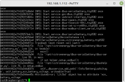
INFO:SerialBattery:=== Settings ===
INFO:SerialBattery:> Connection voltage 49.29V | current 0.0A | SOC 50%
INFO:SerialBattery:> Cell count 15 | cells populated 15
INFO:SerialBattery:> CCL Charge 50.0A | DCL Discharge 60.0A
INFO:SerialBattery:> MIN_CELL_VOLTAGE 2.9V | MAX_CELL_VOLTAGE 3.45V
 
Thx for your effort. New screenshot v.0.12b2. Due to my very limited knowledge i can't read anything leading me to any enlightenment...
1659640488371.png
 
I wonder what is so special about my system? Why me??? ?
Just a PI, BMS and VenusOS...
 
It's always good to be special;)

The problem it seems is that it either cannot read your cell count from the BMS, or more likely the min/max cell voltages you set cannot be read.
It could be that something is breaking it when you edit it, which could be Windows vs Linux line endings, or even regional settings.
If you have access to a linux system there is a tool called dos2unix which fix any Windows characters. The build system for the driver use that on each file when a build is created. See https://github.com/Louisvdw/dbus-serialbattery/blob/log-battery-settings/create_build.sh

You could also run it yourself. It is not available inside the GX system on your Pi - you need another linux system like Ubuntu.
 
Try this file that already has your cell voltage changes.
Copy it to your GX adn extract with this this:

tar -zxf utils.zip-C /data/etc/dbus-serialbattery
 

Attachments

  • utils.zip
    2.1 KB · Views: 15
I'll try this evening, still at work.
But I haven't touched the utils.py at all after the installation, as you said the voltages make no difference except the BMS will stop charging at 3,45V.
Little hope therfore...
 
A complete noob here. Never in my life have I worked with code nor used SSH but trying my best to get this awesome feature installed. I have a JK BMS and Cerbo GX running firmware v.2.89. Using Putty for the first time, I followed the steps in the install github page as well as the Youtube video. Logged into Putty using host name root@venus.local, then entered the password. I then copied and pasted this into the command field (wget https://raw.githubusercontent.com/L...ster/etc/dbus-serialbattery/installrelease.sh). Everything up to this point was going well according to the video. Next, I entered this (sh installrelease.sh) and then it got stuck. Messages say "cant create directory," "no such file or directory," "omitting directory." One thing I later read about is creating SSH keys which I didnt do, but I didnt see that in the install video. Not sure what else I could do differently. Any help would be greatly appreciated.

Another thing I also dont quite understand is how to edit the battery parameters and get those uploaded into the Cerbo using SSH since my understanding is that everything gets downloaded and installed from the internet via the link in the wget command. I did download the folder venus-data.tar.gz and edited the utils file. Now how to get that edited file onto the Cerbo?
 

Attachments

  • 2022-08-08 (6).png
    2022-08-08 (6).png
    1.7 MB · Views: 11
  • 2022-08-08 (7).png
    2022-08-08 (7).png
    1.6 MB · Views: 12
A complete noob here. Never in my life have I worked with code nor used SSH but trying my best to get this awesome feature installed. I have a JK BMS and Cerbo GX running firmware v.2.89. Using Putty for the first time, I followed the steps in the install github page as well as the Youtube video. Logged into Putty using host name root@venus.local, then entered the password. I then copied and pasted this into the command field (wget https://raw.githubusercontent.com/L...ster/etc/dbus-serialbattery/installrelease.sh). Everything up to this point was going well according to the video. Next, I entered this (sh installrelease.sh) and then it got stuck. Messages say "cant create directory," "no such file or directory," "omitting directory." One thing I later read about is creating SSH keys which I didnt do, but I didnt see that in the install video. Not sure what else I could do differently. Any help would be greatly appreciated.

Another thing I also dont quite understand is how to edit the battery parameters and get those uploaded into the Cerbo using SSH since my understanding is that everything gets downloaded and installed from the internet via the link in the wget command. I did download the folder venus-data.tar.gz and edited the utils file. Now how to get that edited file onto the Cerbo?
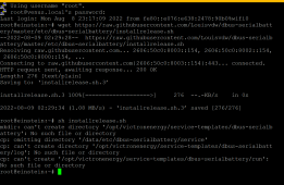
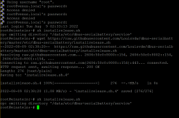
Just reboot and then check the GUI if it picks up else check the log files. It seems that those folders did copy in one of your tries.
You don't need ssh keys - you are using a password.

The easiest way is to edit the parameters inside ssh. (that is the SSH edit using Nano editor from the wiki). Once you changed the parameters you need to reboot your GX device again.
 
What a perfect solution you created Louisvdw! I got it running now for 2 months now with a Daly BMS and it's a very good solution.
My current system consists of a 280Ah 48V Eve Battery with Daly 250A BMS connected via a Victron smartshunt to three Multiplus II 3000VA and two SmartSolar MPPT 250/100's managed by the Cerbo GX.
As I haven't seen many posts about the Daly falling a sleep and just showing no current and sometimes not even visible to the Cerbo which cuts out the MPPT's, I think this problem is related to my Daly BMS. The Smart Shunt is working flawlessly and gives me a good representation of the Soc, but as the Daly sleeps half of the time it hits the boundaries of the SoC and cuts the MPPTs.
I'm currently in the progress of buying another set of batteries and I'm looking to buy its BMS. What is in your opinion the best BMS which works with your solution? And another question... would it be possible/ a good idea to use the Soc of the SmartShunt to manage the ESS system and have a SoC representing both the battery packs?
Thanks a lot for the time you are investing it this solution!!!
 
the Daly falling a sleep
The Daly is not suppose to go to sleep while the driver is querying it. Is there perhaps a setting that you can change for this in the BMS?

What is in your opinion the best BMS which works with your solution
The BMS that people have the least querries/issues are the JBD or JKBMS (JKBMS is also a good option but it seems that the SOC calc for the JBD is a little bit smarter/better. The JKBMS app is easier and less complex).
The Daly gets by far the most issues logged and it's communication protocol is also a bit limiting.

use the Soc of the SmartShunt
The problem is that a BMS will adjust it's SOC when some issues inside the battery occur. For instance if one of your cells go over the cell protection voltage the BMS will show 100% SOC (correctly) while any external shunt (like SmartShunt) will think the SOC is perhaps 85% and push in more charge current. So it is not the best option.
 
Wow, thanks for your incredibly quick reply. I've looked into the first option, but haven't found anything, maybe someone else has found a solution. I figured that the JBD would be my go to BMS and I probably/certainly replace this 'bad behaving' Daly BMS. Your remark concerning the adjustment of the SoC based on Cell Voltage hadn't crossed my mind, so thanks for that. I'm going to look for your Paypal-account on Github, but maybe you want to post it again?
 
If you do keep the Daly for use on your system I would suggest adding an extra cell balancer.

Just click on the link in my footer. It will take you to the github page for this project. The sponsor links is on the top and on the right.
 

diy solar

diy solar
Back
Top