diy solar

diy solar

Conduit termination when plugs are involved

George_Moore

New Member
Joined
May 3, 2022
Messages
24
I am doing a DIY grid tie in Southern California.
I am using 16 panels in 2 strings to a string inverter going into an AC disconnect box before connection to the grid.
I am using a Growatt MIN-6000-TL-X inverter.
The issue is this: This model inverter has simplified installation using external plugs. I cannot terminate conduit to their box, as the box is never opened. All connections are external.
Most instructions I see for other systems show conduit going into the box for DC and conduit coming out of the box for AC. I can't do that.
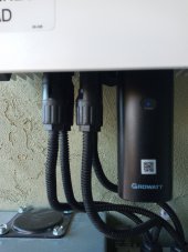
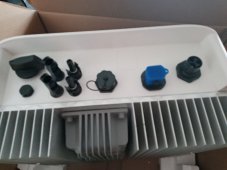
The inverter DC input is through 4 MC4 plugs, 2 for each string.
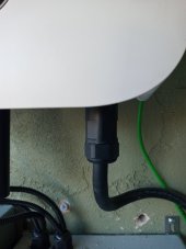
The output from the box is through a large AC plug. I have attached a photo of the bottom of the box.
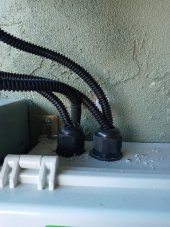
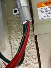
So, I have conduit coming off the roof, and at the end of the conduit my 4 wires come out, which I have attached MC4 connectors to, and they attach to the inverter.

1.) The end of the conduit just sits there with the wires coming out. What is the right thing to do here for compliance?

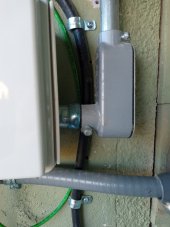
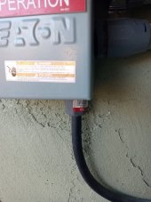
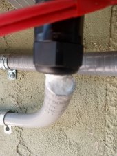
The AC has a plug but I THINK I am not allowed to use SOOW for running the two feet to the AC Disconnect. So, I have 3 wires coming out of the plug on the inverter and they go into liquidtight flexible conduit than then goes to the AC Disconnect. I sealed them with silicon to comply with being watertight, but ...

2. Wires from a plug going into conduit can't be the right thing to do. Is SOOW ok for this, or is there a proper way to make a connection between the plug and the conduit? That is, can I run SOOW from the inverter to the AC Disconnect box?


I have attached some photos. What is the right way to handle the two transitions?
 

Attachments

  • strapped and WP conduit 20220815_124738.jpg
    strapped and WP conduit 20220815_124738.jpg
    486 KB · Views: 20
  • plug end to sealed conduit 20220815_124732.jpg
    plug end to sealed conduit 20220815_124732.jpg
    496 KB · Views: 20
  • Bottom of inverter 20220601_135815.jpg
    Bottom of inverter 20220601_135815.jpg
    551.6 KB · Views: 20
Last edited:
SOOW is service cord, like for a washing machine. You should be fine to run that directly to the inverter outside of the conduit. The silicone in the end of the conduit isn't likely an approved solution. I think a water tight strain relief on the ATS for the SOOW would be my preference.

I'm not sure that AC plug is going to pass safety depending on how you wire the transfer switch it could be hot when unplugged.
 
I would find a electrical box or two to fit against the bottom of the inverter and terminate conduit to them with approved connectors.
 
SOOW is service cord, like for a washing machine. You should be fine to run that directly to the inverter outside of the conduit. The silicone in the end of the conduit isn't likely an approved solution. I think a water tight strain relief on the ATS for the SOOW would be my preference.

I'm not sure that AC plug is going to pass safety depending on how you wire the transfer switch it could be hot when unplugged.
Thank you! The AC plug is built into the Growatt, so I am assuming it is already UL approved. Is ATS Automatic Transfer Switch? I don't have one. Only an AC disconnect provided by SDGE. So that part of the question is, can I run the SOOW from the AC disconnect box? That does look like what is expected by the Growatt people. For the DC conduit, is there such a thing as a water tight strain relief for the end of the conduit or do I need an electrical box?
 
Last edited:
I would find a electrical box or two to fit against the bottom of the inverter and terminate conduit to them with approved connectors.
Thank you! So, put an electrical box on the end of the conduit to the AC disconnect, and run SOOW from there to the AC plug on the inverter?
And for the DC, put an electrical box on the end of the conduit, and run THHN or THWN from there to the MC4 connector on the inverter?
 
Last edited:
The AC plug is built into the Growatt, so I am assuming it is already UL approved. I have never heard of running SOOW to an AC disconnect bot, but that does look like what is expected by the Growatt people.
The Growatt says UL certified, I'm pretty sure that's not a thing. I just checked the UL listing and the only 2 products that come up when searching Growatt are both from Tigo.
 
So, put an electrical box on the end of the conduit to the AC disconnect, and run SOOW from there to the AC plug on the inverter?
And for the DC, put an electrical box on the end of the conduit, and run THHN or THWN from there to the MC4 connector on the inverter?
No use like a 6x6x6 junction box with user located holes to allow it to be nestled snug up underneath the inverter. Connect conduit to it then make what ever wire connections inside it. You need to separate AC and DC unless all wire insulation is greater than the highest voltage in the box.
 
No use like a 6x6x6 junction box with user located holes to allow it to be nestled snug up underneath the inverter. Connect conduit to it then make what ever wire connections inside it. You need to separate AC and DC unless all wire insulation is greater than the highest voltage in the box.
ok, so the DC wires coming off the roof are THWN 10 AWG. I will run the wires through conduit into the 6x6x6 junction box and out again as individual wires to connect to the inverter with the MC4 connectors. I will run AC from the plug into the junction box using SOOW, and from there switch them over to THWN 10 AWG and run them through conduit to the AC disconnect box. Correct? I'm unclear on what you are saying about keeping the AC and DC separate. I think you are saying I ONLY need to keep them separate if the insulation isn't great enough, but the insulation should be ok? So I can mix them in this one box?
 
I am not sure you have a mental picture of it. When you are finished all you can see is the inverter with a box on the bottom. All conduit connections are on the box. It is touching the bottom of the inverter. All of the plugs coming out are inside the box. No soow, no exposed wires of any type.
 
A diy grid tie in so cal ? Did you have to submit plans etc...for a permit? Do you have a net metering agreement? Just curious, seems like it would be quite difficult to get a diy grid tie approved in Cali.
 
A diy grid tie in so cal ? Did you have to submit plans etc...for a permit? Do you have a net metering agreement? Just curious, seems like it would be quite difficult to get a diy grid tie approved in Cali.
Hi! Well, I guess daunting more than difficult. If you can DIY in the first place, then you can get through it. But I made a big mistake in the inverter I chose. (Edit: not such a big mistake after all.) Although technically on the list of accepted inverters, the plugs on the bottom make it non-compliant for conduit termination and exposed wires. (Edit: I got things approved eventually. The inspector accepted the unit when all wires went to proper boxes.) Yes, I have Net Metering, and yes, I had to submit plans. I used an online tool for getting my roof picture and dimensions, and a tool from Ironridge for my rails BOM, and bought them from AltE. Monkwatt drew them. I bought my panels and inverter from Signature Solar (Very helpful). Because my panel is 100A I had SDGE (my power company) put in a device for service side connection rather than going through the panel for load side connection.
 
Last edited:
I am not sure you have a mental picture of it. When you are finished all you can see is the inverter with a box on the bottom. All conduit connections are on the box. It is touching the bottom of the inverter. All of the plugs coming out are inside the box. No soow, no exposed wires of any type.
Oh, I see! When you say snug you really mean snug! Well, the switch is down there, and the wifi dongle too. Might be tricky, but it would solve the problem if I can make it water tight. The extra depth is so I can cross over inside too, correct? Thanks!
 
SOOW is service cord, like for a washing machine. You should be fine to run that directly to the inverter outside of the conduit. The silicone in the end of the conduit isn't likely an approved solution. I think a water tight strain relief on the ATS for the SOOW would be my preference.

I'm not sure that AC plug is going to pass safety depending on how you wire the transfer switch it could be hot when unplugged.
You were right on all counts. Especially the silicon. Turned out I got an electrician to fix things properly. The conduit was terminated to a box that also held my RSD device transmitter. From there DC goes to the MC4 connectors. The AC plug with SOOW goes to the box for the RMA device installed by SDGE (my service provider). This is where my AC comes in. When the breaker in the box is flipped, the AC from the Inverter senses it and shuts down. The AC plug is then not hot.
 
George, I am dealing with the same exact situation here in Maine. Could you post a picture of your final install of the inverter that shows the transitions from conduit to the bottom of the inverter? Thanks! Mike
 
George, I am dealing with the same exact situation here in Maine. Could you post a picture of your final install of the inverter that shows the transitions from conduit to the bottom of the inverter? Thanks! Mike
Okay. This is a Growatt MIN 6000TL-X inverter. It is a sealed box with connectors on the bottom. (1) DC from roof terminates to an electrical box. I wanted rain tight type LL conduit body, but my electrician said I didn't need it in the alcove because it is covered, so he used a set screw type LB. The electrical box houses my Tigo RSD transmitter. DC runs through my RSD transmitter for Power Line Control (PLC) transmission. Although not shown in these pictures, it has AC in from my panel to power the transmitter, and when power is shut down it cuts it off. (I don't have (or need) a fancy DC disconnect switch but I'm going to add a "mushroom" push button stop to turn off the transmitter, even though it isn't necessary. When power is cut at the main the transmitter stops) (2) DC comes out at the top of the box, I added some split plastic covering to help protect from any sun, even though this is in a covered alcove. (3) DC goes to MC4 connectors, which connect to the Inverter. (It's a really short run. Maybe I should have used just one picture for clarity.) There are 4, as I have two strings, but the two in the back are hard to see in the picture. This passed before I added the wire covers, but I think it is okay I added them. You can see the wireless datalogger in the same shot. (4) The Inverter output is in the form of a plug, with L1, N, and Gnd. My electrician used SOOW, but my inspector would have preferred liquidtight conduit if I could make it work. I think the SOOW is actually better, as the plug was obviously designed for it. (4) The SOOW cable goes to the RMA box installed by SDGE (My power company) for service side connection. Most people upgrade their service panel instead, and this would go to the service panel. L1 and N go across the 240V in what is called single phase or split phase configuration. There is some confusion as to what that means on the net, so read up on it, but essentially that's all it means. The inverter puts out 240 V that goes across a double breaker to the 240V that comes in from the grid. The inverter will power up the panel when it has enough DC in, but will not output anything until it is tied to the grid and senses the grid power. Let me know if you want any more pictures. Although daunting, it is actually very straight forward.
 

Attachments

  • conduit termination to electrical box.jpg
    conduit termination to electrical box.jpg
    147.3 KB · Views: 13
  • DC from electrical box.jpg
    DC from electrical box.jpg
    216.4 KB · Views: 13
  • DC to MC4 connectors.jpg
    DC to MC4 connectors.jpg
    160.5 KB · Views: 12
  • AC out from inverter  to SOOW cable.jpg
    AC out from inverter to SOOW cable.jpg
    97.8 KB · Views: 12
  • SOOW cable into RMA box connection to grid.jpg
    SOOW cable into RMA box connection to grid.jpg
    156.4 KB · Views: 13
Okay. This is a Growatt MIN 6000TL-X inverter. It is a sealed box with connectors on the bottom. (1) DC from roof terminates to an electrical box. I wanted rain tight type LL conduit body, but my electrician said I didn't need it in the alcove because it is covered, so he used a set screw type LB. The electrical box houses my Tigo RSD transmitter. DC runs through my RSD transmitter for Power Line Control (PLC) transmission. Although not shown in these pictures, it has AC in from my panel to power the transmitter, and when power is shut down it cuts it off. (I don't have (or need) a fancy DC disconnect switch but I'm going to add a "mushroom" push button stop to turn off the transmitter, even though it isn't necessary. When power is cut at the main the transmitter stops) (2) DC comes out at the top of the box, I added some split plastic covering to help protect from any sun, even though this is in a covered alcove. (3) DC goes to MC4 connectors, which connect to the Inverter. (It's a really short run. Maybe I should have used just one picture for clarity.) There are 4, as I have two strings, but the two in the back are hard to see in the picture. This passed before I added the wire covers, but I think it is okay I added them. You can see the wireless datalogger in the same shot. (4) The Inverter output is in the form of a plug, with L1, N, and Gnd. My electrician used SOOW, but my inspector would have preferred liquidtight conduit if I could make it work. I think the SOOW is actually better, as the plug was obviously designed for it. (4) The SOOW cable goes to the RMA box installed by SDGE (My power company) for service side connection. Most people upgrade their service panel instead, and this would go to the service panel. L1 and N go across the 240V in what is called single phase or split phase configuration. There is some confusion as to what that means on the net, so read up on it, but essentially that's all it means. The inverter puts out 240 V that goes across a double breaker to the 240V that comes in from the grid. The inverter will power up the panel when it has enough DC in, but will not output anything until it is tied to the grid and senses the grid power. Let me know if you want any more pictures. Although daunting, it is actually very straight forward.
George, this was perfect.. just what I needed. I am putting in almost an identical Min-5000-TL-X from Signature solar and will be using Tigos too. (I went online and took their short course and exam). I will have an inside connection (I'm within the 120% rule on my distribution box bus). What you did with the electrical box and the pigtails to the inverter MC4/DC connections is exactly what I was hoping I could do! Thank you so much! Mike
 
Back
Top