Ampster
Renewable Energy Hobbyist
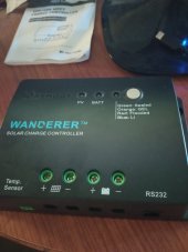
No but a quick check indicates that the Wanderer has a voltage setting for several chemistries, which suggests that it is there for a reason, perhaps to prevent overcharging,. The one I looked at had different settings for Gel, Flooded, AGM and Lithium. If those were not voltage settings why would they give you those options?Have you used a Non-Programable PWM Charger designed for Lithium Iron Phosphate like the Renogy Wanderer - that has been recommended several times by WIll? With this Solar Charge Controller, you can not program it, and the only way it stops charging is when the battery BMS turns off the charging current and stops accepting charge into the battery.
"or what about a simple wall charger that charges the battery until the batteries BMS kicks in?"
If it is the correct wall charger it outputs the correct voltage for th
"Or, what about the concept of a "Drop In Replacement LIFEP04 Battery?"
What about the concept of a Drop in Replacement Battery?. Most of the ones I have seen suggest a target voltage for charging. I am sure given that they are marketed as drop ins that they are designed to withstand abuse by people who follow any YouTube video.