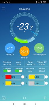
You just said they are hot. Any heat is due to resistance. Resistance=voltage drop. Not sure why you are still so reluctant to accept that the cables have issues. Someone calculated about 33 watts being dissipated. It's not like that is going to make the cables glow or anything
And you would get more if you weren't loosing it to heat in your cables.
After you get the cable issue fixed, I highly recommend you crank the controller down to the recommended charge voltage and stop relying on the BMS to cut things off.
.
Hi, I don't know if I am supposed to reply to everyone who replies to me, due to me repeating my plans and answers, so if you already read my most recent replies, sorry.
Thank you for your very insightful analysis on this. 33 watts is a lot of energy and I think you guys might be right. I don't know why 8 Gauge AWG Thin Strand Silicon Cables wouldn't be able to handle HALF their rated Amps, but as I have already said several times, I will be swapping that out with a 6 Gauge AWG Cable and double checking all the connections, etc. I am all about keeping things as cool as possible and as efficient as possible.
There seem to be a lot of people in this forum who think it is a bad idea to use the BMS to stop the charging cycle. The way I see it, and the way I have seen literally every person on YouTube who does battery capacity tests AND MORE - including the Man himself ^ - they all let the BMS "do its job" and cut off the charging cycle when the battery is full.
For the first 2 years all I used was a simple PWM Charge Controller, and there was no way to program it, other then select the "Blue Light" for Li. (Renogy Wanderer 30 Amp LFP Model) and the Battery would charge until it was full and cut off.
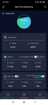
Even with my new MPPT Controller, there really is no way to stop it from sending energy into my battery, I literally have no way at all to stop it from charging, and I have to rely on my BMS to halt the charge cycle.
Am I missing something?
Aggressive settings; Yea, I LOVE THEM and I am getting more juice into my system then ever before and to quote myself:
"
As for the charge controller settings, I appreciate your concern, and your caution. But I have been playing with this for about a week and I am very happy with the function and operation of my system, it is working great, and it is mid summer, very hot, and everything is working great. Again, will upgrade that wire for efficiency & peace of mind.
As we move into the cooler Fall months, I will continue to monitor and use the system daily, cooking, and even seeing if I can cook and run a small 12v 300 watt heater, and have enough juice. I will monitor the system and I will report back on the progress. I have confidence in my Batteries, and though I may be "shaving years off of them" by using aggressive charging parameters, I am more than sure they will hold up just fine for a very long time, and if not, its not a big deal, they are the cheapest Chinese Packs I could get from China. They could fail for any reason at any moment, and if they die, they die. Based on the safety data on these batteries, there is more of a chance that any other component will fail before the battery cells themselves fail, and if that happens I will tear them apart and harvest them. "
Thank you for all your great help and advice. Thanks.