diy solar

diy solar

Does anyone do DC system diagram consultations? I'll pay!

Dustmopper

New Member
Joined
Sep 1, 2022
Messages
12
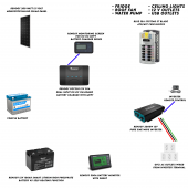
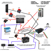
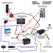
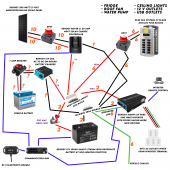
I'm 90% sure that I have everything I need but I would like an expert second opinion to fill in the blanks and answer a few questions. Here is a diagram of the system I plan on putting into a small van (Nissan NV200).

I am looking for someone to fill in the needed breakers, fuses, bus bars and appropriately sized wires.

This system is very similar to the 400 Watt diagram already on this website.

I also have a few general questions:
  • Unfortunately I only have room for one solar panel, is a 200 Watt enough for a 12V 100AH battery?
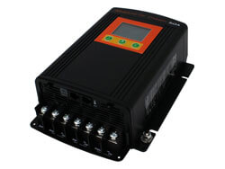
  • Is the 30A DC-DC Battery Charger big enough with only a 200W solar panel and the vehicle battery or should I upgrade to the 50A?
  • Is a 12V 100AH battery powerful enough to run a 2000W inverter? I can downgrade to the 1000W inverter if necessary.
Other notes:
I don't expect my AC demand to be too high, I'm not living in this full time. Also, I would like to put in the Renogy Shunt as a battery monitor. I expect that the majority of my battery charging needs will come off of the alternator and not from solar, I will be doing more driving than boondocking. I have experience wiring AC outlets and breakers. However, DC is completely new to me and I want to double check the wire and breaker sizing. I do not have the van yet so I cannot give you information on the vehicle battery or alternator.

You can see that I have chosen Renogy for all this, I just figured it would be easier to get everything from one place. If you have better suggestions please let me know. I saw that their inverters are not highly recommended on this website but I wanted one with an AC Terminal so I can wire up a few GFCI outlets.

If someone with experience wiring mobile systems like this feels like they can fill in the blanks on my diagram and answer some questions please send me a quote to do so. I strategically left room on the image for breakers, fuses, wires, bus bars, etc.

Thanks!
 

Attachments

  • Electrical Diagram.png
    Electrical Diagram.png
    343.7 KB · Views: 23
Renogy support sucks.
Those combo dc2dc/mppt chargers have not garnered a good reputation on the forum.
That battery is expensive but it does not a bluetooth interface so you don't need a shunt.

That battery can't even come close to powering a 2000 watt inverter.
2000 ac watts / .85 conversion factor / 10 volts low cutoff = 235.294117647 service amps
235.294117647 service amps / .8 fuse headroom = 294.117647059 fault amps.

You would need 3 of those batteries in parralel to power that inverter.
I suggest the 700 or 1000 watt inverter instead, depending on whether your need hardwire capability or not.
 
This may not help you, but earlier in my solar journey I found that Midnite Solar (makes solar equipment for many years) has many example wiring diagrams online. Google "Midnite Solar Wiring Diagrams" and see things like this - e.g. panels -> charge controller w/lightning arrestor (surge protection), circuit breakers including a DC ground fault -> + / - fuse blocks (for battery/load hookups). The "MNPV6" is just a combiner box (other models will work or DIY will work). The "Model #MNDC-GFP80" is a recommended DC ground fault breaker - which you may or may not want/need - but it's good to know about.

1662062895016.png

Here's an entire page on various diagrams - https://www.midnitesolar.com/documentsA.php

Perhaps other vendors have wiring diagrams as well. I understand it can be overwhelming, but if you trace out something (like the pic above) it should begin to make sense with some research - and will only help you hookup you're own system with confidence.
 
Last edited:
Here is a textual representation of your components except for the shunt.
The legend block explains the dc_domain block.
 

Attachments

  • Dustmopper.txt
    1.2 KB · Views: 24
Here is a textual representation of your components except for the shunt.
The legend block explains the dc_domain block.
Thank you for your advice and for assembling this diagram. I will downgrade to the 1000W inverter and cancel the shunt. Is there a program that I need to visualize this text file from code into an image?

Thanks again!
 
Thank you for your advice and for assembling this diagram. I will downgrade to the 1000W inverter and cancel the shunt. Is there a program that I need to visualize this text file from code into an image?
Not until I write one.
Its code but its also human readable.
The systems we make look like ladders the busbars are the risers and the circuits are the rungs.
Notice the first thing in the dc_domain is the busbars.

Updated for 1000 watt inverter.
 

Attachments

  • Dustmopper.txt
    1.2 KB · Views: 13
Not until I write one.
Its code but its also human readable.
The systems we make look like ladders the busbars are the risers and the circuits are the rungs.
Notice the first thing in the dc_domain is the busbars.

Updated for 1000 watt inverter.
Yes actually once I took a second to figure out the code that text file was extremely helpful. I have put together another version of my diagram using your information. Please take a look when you get a chance and let me know what you think.

The DPST, Breakers and wires should be sized correctly. Do you have a recommendation for the busbars I should get?

Thanks a million!
 

Attachments

  • Electrical Diagram V3.png
    Electrical Diagram V3.png
    556.1 KB · Views: 27
The main battery fuse needs to have a breaking capacity of at least 10000 amps
The basically means an mrbf fuse.
This is an mrbf fuse in a terminal carrier.
It fits right on the battery terminal making an upstream short virtually impossible.

Use this for your positive busbar.
It also uses mrbf fuses

Use this for the negative side
You will have to stack some lugs.
Put the battery and inverter on the same lug.

The dpst is actually one breaker that does both wires.

Its hard for me to see but it looks like you got it all correct.

For the ac domain I think that all you need is a power strip and
possibly and extension cord.

You only have 1000 watts.
Are you sure that is enough?
 
Use the 200 amp mrbf fuse for battery circuit.
Use the 150 mrbf fuse for the inverter circuit.
 
I just realized you didn't give any details on the panel.
Better check those because that combo controller has a very low max pv voltage.
 
I just realized you didn't give any details on the panel.
Better check those because that combo controller has a very low max pv voltage.
I have made those adjustments an attached an updated diagram.

It makes sense that the DPST would take both positive and negative. I think 1000W for the inverter will do. I don't anticipate a high AC load. Just a laptop charger and some other small things. I'll make sure if I use any kitchen appliances that they don't exceed 800W and nothing else runs when I use them.

I upgraded the diagram for the 50A DC to DC charger although the maximum solar input voltage is only 25V. The optimum operating voltage of the 200W solar panel is 22.6V. I'll add a 15A in-line fuse to the solar connection as well.


Thank you so much for your help with all this. You really seem to know what you're doing!
 

Attachments

  • Electrical Diagram V4.png
    Electrical Diagram V4.png
    528.5 KB · Views: 11
I have made those adjustments an attached an updated diagram.

It makes sense that the DPST would take both positive and negative. I think 1000W for the inverter will do. I don't anticipate a high AC load. Just a laptop charger and some other small things. I'll make sure if I use any kitchen appliances that they don't exceed 800W and nothing else runs when I use them.

I upgraded the diagram for the 50A DC to DC charger although the maximum solar input voltage is only 25V. The optimum operating voltage of the 200W solar panel is 22.6V. I'll add a 15A in-line fuse to the solar connection as well.


Thank you so much for your help with all this. You really seem to know what you're doing!
Ok we may have to adjust for the 50 amp charger.
What is the round trip distance between the starter battery and the combo charger?
Also that panel voltage is uncomfortably close to the combo chargers max pv voltage.
The panel can exceed its VOC=open circuit voltage if its colder than standard test conditions.
 
I was hoping for the combo to save space but it might be better to just have a DC-DC and a Solar Charge Controller

Do you think 20A would be enough? They also come in 40 & 60.
Its all based on your consumption.
The first step in this whole process is an energy audit.
These have a 50 volt pv limit

You never answered my question about the round trip distance between alternator and combo charger.
Also can your alternator handle an extra 30-50 amps at idle without burning up?
I'm not really sure. I haven't bought the van yet, ha ha. I'm going to buy it in the spring so I have all summer to build. I've just been watching endless youtube videos and thinking a lot about the construction and electrical system I need.
 
I'm not really sure. I haven't bought the van yet, ha ha. I'm going to buy it in the spring so I have all summer to build. I've just been watching endless youtube videos and thinking a lot about the construction and electrical system I need.
We may have to tweak the wire and breaker on that circuit to account for voltage drop.
 
We may have to tweak the wire and breaker on that circuit to account for voltage drop.
Alright I have reworked this again to remove the combo charger and add both a solar charge controller and a DC to DC battery charger.

This means that we are out of open spots on the MRBF Fuse Block so we will either have to double stack two of the 100A onto the same fuse or perhaps break out the Inverter onto its own 150A ANL fuse, separate from the block entirely.

I also dropped in another DPST for the DC Fuse block to make it easier to add and remove appliances and fuses.

The only questions now are the wire sizing and MRBF fuses needed for the two new components. Also the breaker size and wire gauges for the vehicle battery, but it sounds like we won't know that until I actually have the van and can determine the length of the wire run.

The diagram looks confusing at first glance but it all makes sense to me, ha ha.

Thanks again for your help with this!
 

Attachments

  • Electrical Diagram V5.png
    Electrical Diagram V5.png
    582.3 KB · Views: 16
Alright I have reworked this again to remove the combo charger and add both a solar charge controller and a DC to DC battery charger.

This means that we are out of open spots on the MRBF Fuse Block so we will either have to double stack two of the 100A onto the same fuse or perhaps break out the Inverter onto its own 150A ANL fuse, separate from the block entirely.
You can't double stack a fused busbar.
Need to pick another fused busbar.

Here is the chevy option
Notice that all the positions are fused so the battery circuit will be double fused.
Oh well.
waytek has them for a good price.
I suggest you get the either the 5 or 7 port version with 8mm studs.
And 8mm zcase fuses.
Still need an MRBF fuse for the battery though.
I also dropped in another DPST for the DC Fuse block to make it easier to add and remove appliances and fuses.
You don't need a double pole disconnect for the dc fuse block.
A single pole disconnect will be fine.
The only questions now are the wire sizing and MRBF fuses needed for the two new components.
The fuses and breakers are sized to the wire.
6 awg gets 100amp over-current protection
4 awg gets 150amp over-current protection
2 awg gets 200amp over-current protection
0 awg gets 250amp over-current protection
00 awg gets 300amp over-current protection
0000 awg gets 400amp over-current protection

For things with cage clamps like that solar charge controller, I generally use the largest wire that will fit.
For mobile applications fine stranded wire(welding cable) is preferred.
For fine stranded wire I like to use ferrules to keep the strands from shorting to the adjacent terminal.

The solar charge controller has a max wire size of 8 awg.
Since its only 20 amps I suggest to land it on the fuse_block using 10 awg wire and a 30 amp fuse.

Also the breaker size and wire gauges for the vehicle battery, but it sounds like we won't know that until I actually have the van and can determine the length of the wire run.
Correct.
The diagram looks confusing at first glance but it all makes sense to me, ha ha.
Thanks for taking the time.
Thanks again for your help with this!
You are welcome.

Will update the drawing.
 
Those fhz busbars and zcase fuses are so inexpensive I use them for the negative busbar too.
I just put zcase fuses under the busbar instead of over.
 

Attachments

  • Dustmopper.txt
    1.4 KB · Views: 9

diy solar

diy solar
Back
Top