diy solar

diy solar

Does anyone do DC system diagram consultations? I'll pay!

When you get your solar charge controller and dc2dc charger could you please do me a favour.
I would like you to check for continuity between the negative terminals.
If they have continuity between the negatives then they are non-isolated chargers and I will change the topology to reflect that.
 
Those fhz busbars and zcase fuses are so inexpensive I use them for the negative busbar too.
I just put zcase fuses under the busbar instead of over.
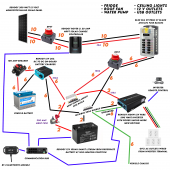
OK here is V6, I have followed your latest text file instructions.

My problem is that I keep thinking of this as a series of inputs (solar/dc-dc) and outputs (dc fuse block / inverter) instead of as one closed system.

I wouldn't have thought about connecting the 20A solar charge converter into the fuse block. By doing that we don't need to change the MRBF Positive Busbar either because we still just have 4 connections.

I was worried about putting 30A solar into the fuseblock with a max of 100A but then I looked up some of the other appliances and it appears that the fridge runs at 5A (60W/12V) and the ceiling fan is at 4A so I think we'll be alright.

Thanks again! This whole system looks pretty solid not super complicated once you start to understand it.
 

Attachments

  • Electrical Diagram V6.png
    Electrical Diagram V6.png
    584.2 KB · Views: 13
You don't need or want a double pole single throw disconnect switch between the positive busbar and fuse_block.
You might want a single pole single throw disconnect switch.

Please stop making me look at the drawing, its going to give me nightmares.
 
You don't need or want a double pole single throw disconnect switch between the positive busbar and fuse_block.
You might want a single pole single throw disconnect switch.

Please stop making me look at the drawing, its going to give me nightmares.
Fair enough, ha ha. It does make you go cross-eyed when you look at it too long.

Here is a simple DC on/off switch that I'll put on the positive line to the fuse block instead of using a DPST. Thanks again!
 
Ok the battery has a bluetooth interface which should gives you a means of administrative disconnect.
The inverter has an on/off switch as its means of administrative disconnect.
The solar charge controller has a dpst on the pv side as its means of administrative disconnect.
The dc2dc charger has a breaker as its means of administrative disconnect.
That is everything but the fuse block.
You don't need one on the fuse block because everything else has one.
But if you really want one that Bluesea that you linked is a good one.
 
The main battery fuse needs to have a breaking capacity of at least 10000 amps
The basically means an mrbf fuse.
This is an mrbf fuse in a terminal carrier.
It fits right on the battery terminal making an upstream short virtually impossible.

Use this for your positive busbar.
It also uses mrbf fuses

Use this for the negative side
You will have to stack some lugs.
Put the battery and inverter on the same lug.

The dpst is actually one breaker that does both wires.

Its hard for me to see but it looks like you got it all correct.

For the ac domain I think that all you need is a power strip and
possibly and extension cord.

You only have 1000 watts.
Are you sure that is enough?
Would the mrbf fuse work for a parallel connection between 48v batteries? I'm basically trying to isolate each battery in case of a fault so they can't feed into one another.
I would rather have a circuit breaker so I could turn them off individually if necessary, would the T tocas 150 amp CB work for this?

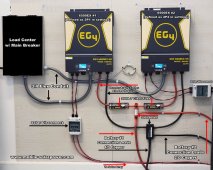
I already have all the other necessary items according to Will's eg4 48v build on his website.

Here's the planned layout of one of the batteries. I will install the batteries with the main positive and negative facing each other.
20230110_121422.jpg

Lvx 6048 X2 in parallel 12kw total
16s4p 302AH 3V cells
200amp DC breakers with 10ka arc extinguishable.

Screenshot_20230114-132023_DuckDuckGo.jpg
 
Would the mrbf fuse work for a parallel connection between 48v batteries? I'm basically trying to isolate each battery in case of a fault so they can't feed into one another.
I would rather have a circuit breaker so I could turn them off individually if necessary, would the T tocas 150 amp CB work for this?

I already have all the other necessary items according to Will's eg4 48v build on his website.

Here's the planned layout of one of the batteries. I will install the batteries with the main positive and negative facing each other.
View attachment 129617

Lvx 6048 X2 in parallel 12kw total
16s4p 302AH 3V cells
200amp DC breakers with 10ka arc extinguishable.

View attachment 129615
I wouldn't use a T-Tocas breaker for any application.
The MRBF fuse is good kit but they don't have the breaking capacity to be used with 48 volt nominal LFP batteries.
My preferred over-current protection for LFP batteries of 24 or 48 volts nominal is a class-t fuse.
Also I prefer to peer each battery to the main system busbars.
It makes each battery independent which is a good thing for moves, adds and changes.
If you wish to talk about overall system topology I will be glad to help.
20220523-124534.jpg
I have basically everything in this layout.
The main difference is I will install the batteries directly below this and I have 4 batteries as described above.

Would I need 4 Tclass fuses to keep one battery from feeding into another battery in case of a fault? And where would be the best place to put them?

Is there a circuit breaker option instead of Tclass fuses so I can manually shut each battery down if needed? The main reason for this option would be to avoid another set of connections for a manual switch.
 
View attachment 129629
I have basically everything in this layout.
The main difference is I will install the batteries directly below this and I have 4 batteries as described above.

Would I need 4 Tclass fuses to keep one battery from feeding into another battery in case of a fault? And where would be the best place to put them?

Is there a circuit breaker option instead of Tclass fuses so I can manually shut each battery down if needed? The main reason for this option would be to avoid another set of connections for a manual switch.
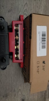
Did you purchase busbars yet?
 
Here is the math...
6500 ac watts / .85 conversion factor / 48 volts low cutoff = 159.31372549 inverter amps
159.31372549 inverter amps / .8 fuse headroom = 199.142156863 fuse amps
Since you will have 2 inverters you need a busbar that can handle 400 fault amps.
It should have 6 positions, 2 fused positions for the inverters and 4 un-fused positions for the batteries.
320 inverters amps / 4 batteries is 80 amps per battery.
That is asking a lot from those batteries.
 
I suggest this
Use this video to learn how to fuse the inverter circuits.
 
Here is the math...
6500 ac watts / .85 conversion factor / 48 volts low cutoff = 159.31372549 inverter amps
159.31372549 inverter amps / .8 fuse headroom = 199.142156863 fuse amps
Since you will have 2 inverters you need a busbar that can handle 400 fault amps.
It should have 6 positions, 2 fused positions for the inverters and 4 un-fused positions for the batteries.
320 inverters amps / 4 batteries is 80 amps per battery.
That is asking a lot from those batteries.
You just completely lost me. The specs on my inverters are nowhere near all of what you just posted.
 
@Brettw what inverters do you have?
Do you have the eg4 rack with busbars per chance?

UPDATE: My mistake I see you are using diy batteries.
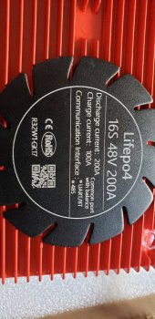
What is the continous rating on the BMSs you are using?
 
@Brettw what inverters do you have?
Do you have the eg4 rack with busbars per chance?

UPDATE: My mistake I see you are using diy batteries.
What is the continous rating on the BMSs you are using?
Lvx 6048 inverters, I posted a link to the specs in the last post.
20230114_150120.jpg
 
Lvx 6048 inverters, I posted a link to the specs in the last post.
6000 ac watts / .85 conversion factor / 48 volts low cutoff = 147.058823529 inverter amps
147.058823529 inverter amps / .8 fuse headroom = 183.823529412 fuse amps
183.823529412 fuse amps * 2 inverters = 367.647058824 aggregate fuse amps

Each battery should use 4 awg wire with a 150 amp class t fuse
The inverters should use minimum 1/0 with a 250 amp fuse.
The lynx system uses mega fuses which are fine for the inverter circuits.
 
Here is a textual representation of the topo
 

Attachments

  • Brettw.txt
    686 bytes · Views: 7

diy solar

diy solar
Back
Top