diy solar

diy solar

Megarevo RxLNA Discussion

I have my Megarevo connected to the grid, self consume, net meetering and Load 1 to a subpanel, CTs are pointing to the grid in the main panel.
Grid DOD is 20% and Off Grid is 80%
Firmware ARM V1.03.12 and DSP V2.04.12

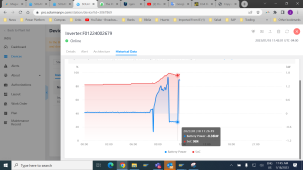
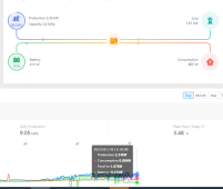
The system is exporting to the grid when battery reach 99-100% as expected but for some reason the battery is discharging at the same time as you see in the picture.

Is this is a normal behavior or there is something wrong with the setting or the firmware?


View attachment 130291

View attachment 130294
I find that picture where you drew the arrows very often not in sync with reality.
What does your battery data show you ?
I made a new template for batteries like this:
Screenshot from 2023-01-18 07-25-23.png
click on "select parameters"
hit "clear" one time
scroll down to "battery" and select "battery power" & "SoC"
Screenshot from 2023-01-18 07-26-20.png
click on "save as template"
I named mine "battery data"
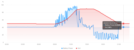
Now I get graph like this
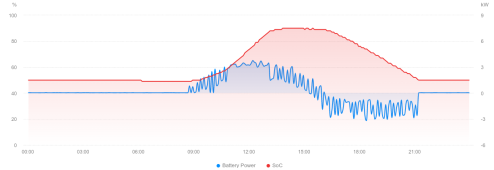
Screenshot from 2023-01-18 07-23-27.png
I have set my inverter to discharge to 50% (to 0% in case grid disappears) .
Red line is State of Charge, and blue shows me when and how much (when you move mouse pointer over the graph) the battery is charging/discharging.

That data is way more accurate than the overview data.
 
Last edited:
Thanks for your answer

Battery reached 100% then started discharging and now it is charging again when battery down to 96%

1674056747083.png
 
I can not explain what you are seeing.
I could be a setting, it could be firmware issue.
Have you considered upgrading to the latest/gratest?
I'm waiting for the USB A to USB A cable to arrive to upgrade the firmware, but is taking forever in USPS. I will check my settings in the afternoon with this manual that GSL send me today and see what happens.
 

Attachments

  • R8KLN(8KW) with GSL battery.pdf
    7 MB · Views: 32
Just as a heads up, my inverter uses USB-C at the inverter side, not USB-A. I'm not sure if there are different revisions.
 
I was about to write a positive review of the last firmware posted above. But I got a call from the power company today that the metering group is seeing a small amount of back feed into the grid. I don't have a contract for net metering.

With the old June? firmware I was seeing about 50-75 watts/leg of feed in from the grid. With this new firmware I am near zero to slightly below. The new CT setting does not seem to offer any adjustments. I know that Dye has a setting to adjust the amount of grid feed so that the inverter does not over shoot and feed into the grid. I can say that the reaction of the MR has been improved and the over shoot is much less and more stable then before.

I have some new CT's coming tomorrow to test. Does anyone have a know about them, for example the OEM CT is 100 amp/1v. Is my thinking correct that a 100amp/.5v would take twice as many amps for the same output voltage? If so this should raise the input amount from grid or double it putting me back to the 50-75 watt area again like before.

I will go ahead and list the other pro of the new firmware. I am able to charge at a higher rate without it dropping out. I saw 125 amps today where before anything above 90 would cause drop outs when the battery reached above 75% SOC. And like I slightly stated above it seems the reaction of the inverter to changing loads has been improved.
 
The CTs are certainly 1000:1 turn ratio. 100 amps thru the CT will measure 100mA at the leads.

I also tried 100:1 CTs and verified the "incorrect" reading at the leads and on the inverter display.
 
The CTs are certainly 1000:1 turn ratio. 100 amps thru the CT will measure 100mA at the leads.

I also tried 100:1 CTs and verified the "incorrect" reading at the leads and on the inverter display.
Is the MR is looking for an amp input and not a voltage input. So the OEM CT has a diode across the leads and not a burden resistor? I am studying but a complete dummy when it comes to CT. The ones I am using are current but nothing between the leads. The OEM does have what looks like a diode?
 
I have a question about CTs installation. Right now I have my inverter connected to a 40 amp breaker from the main breaker panel and I have a subpanel for Load 1. Work mode is self consume and I'm exporting to the grid.

The CTs are installed in L1 and L2 from the main panel and pointing to the grid. Is that installation is correct or do I need to install the CTs in the Inverter L1 and L2.

If there are installed in the L1 and L2 of the main panel I can see my whole house, not sure is that is the purpose or if they need to be in the Inverter L1 and L2 to see what is coming from the grid to the inverter.

Thanks
 
Is the MR is looking for an amp input and not a voltage input. So the OEM CT has a diode across the leads and not a burden resistor? I am studying but a complete dummy when it comes to CT. The ones I am using are current but nothing between the leads. The OEM does have what looks like a diode?
From what I have tested (I'm new to this too) the output is in mA. Keep in mind this is AC. So you have AC flowing thru the CT, you will measure AC with your meter at the leads.
 
Not sure if I can post a video. This is NOT with the Megarevo CT (ratio is wrong) but same idea.

(nope, no video)
 
I have a question about CTs installation. Right now I have my inverter connected to a 40 amp breaker from the main breaker panel and I have a subpanel for Load 1. Work mode is self consume and I'm exporting to the grid.

The CTs are installed in L1 and L2 from the main panel and pointing to the grid. Is that installation is correct or do I need to install the CTs in the Inverter L1 and L2.

If there are installed in the L1 and L2 of the main panel I can see my whole house, not sure is that is the purpose or if they need to be in the Inverter L1 and L2 to see what is coming from the grid to the inverter.

Thanks
It is my understanding that they should be on the main L1/L2 coming from the meter INTO your main panel. This tells the inverter everything that your house is using. The inverter will then try to "backfeed" your main panel to supplement the load so it pulls near zero from the grid.

Example: If the inverter see 30amps coming into the panel on the CTs, it will try to push (nearly) 30A on the grid terminals to feed back to your main panel to offset the draw from grid. This happens very quickly, so ideally the draw from the grid should never go over a few hundred watts. Unless, of course, there isn't enough PV or battery to supplement the full load.
The problem that I’m seeing in my house is the battery is used to supply the loads in the main panel. I was thinking the battery only supply to Load 1 but is back feeding to main panel too.
 
The problem that I’m seeing in my house is the battery is used to supply the loads in the main panel. I was thinking the battery only supply to Load 1 but is back feeding to main panel too.
If you don't want to feed back into the grid, change this setting:
1. -- SYS SETTING --
[SNIP]
7: Anti Reverse -> 1. DISABLE <- change that to ENABLE and your inverter _should not_ feed back into the grid [ famous last words]
 
If you don't want to feed back into the grid, change this setting:
1. -- SYS SETTING --
[SNIP]
7: Anti Reverse -> 1. DISABLE <- change that to ENABLE and your inverter _should not_ feed back into the grid [ famous last words]
I want to export because I have net metering but not from my batteries. The issue is the inverter is using the battery to feed loads in the main panel. I was thinking the battery only supply to Load 1 output.
 
I want to export because I have net metering but not from my batteries. The issue is the inverter is using the battery to feed loads in the main panel. I was thinking the battery only supply to Load 1 output.
If you do NOT want to feed the main panel then the CT should be on the inverter's grid connection. If you want to feed the main panel then the CT should be on the meter side of the main panel.

I don't have any experience with Peak Shift mode which I think you need to be using. But viewing the manual it looks like anytime you have discharge time entered it will use battery to supply to grid. On charge time or a period of no charge or discharge it looks like it should not use the battery to discharge to grid.
 
I want to export because I have net metering but not from my batteries. The issue is the inverter is using the battery to feed loads in the main panel. I was thinking the battery only supply to Load 1 output.
Looking closer at your graph, your system seems to be feeding about 400 watt from the battery power into the grid.
Let's wait till you have upgraded firmware and see if it still does that.
 
Looking closer at your graph, your system seems to be feeding about 400 watt from the battery power into the grid.
Let's wait till you have upgraded firmware and see if it still does that.
I will try to update the firmware this week. This is another example. I have a production of 2.24kw and my consumption is 865w, then the system is feeding the grid and discharging the battery with about 400w

1674148755032.png
 
I will try to update the firmware this week. This is another example. I have a production of 2.24kw and my consumption is 865w, then the system is feeding the grid and discharging the battery with about 400w
Don't you have a charge cord for a USB-C phone ? that is basically the cable you need to upgrade ;-)
 
Don't you have a charge cord for a USB-C phone ? that is basically the cable you need to upgrade ;-)
I did the upgrade today with the December firmware not sure if is good or not. Still charging the battery from the grid in the night at 50w. I will see tomorrow if still discharging 400W when exporting to the grid
 
I did the upgrade today with the December firmware not sure if is good or not. Still charging the battery from the grid in the night at 50w. I will see tomorrow if still discharging 400W when exporting to the grid
I see between 30-50 but mostly 40 watt from the grid into my battery after sunset and my battery has reached my DoD for self supply:

Screenshot from 2023-01-19 22-59-55.png
With the current setup and angle of my panels relative to the sun at this time of year and my load (electric resistive heating) my batteries never get near to 100% full, so I can not verify the same behavior you are seeing.
 
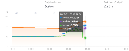
The inverter still sending battery power to the grid when feed-in with the December firmware. I tested with EPS Disable and Grid DOD 0% and still sending battery power to the grid. Also the firmware is messing up with the BMS display information.
I'm going to monitor everything during the day and change the firmware in the night to the one that enable Generator and test it tomorrow.

1674229728582.png
 

diy solar

diy solar
Back
Top