diy solar

diy solar

Easun SMX-II 3.6kW old firmware needed

SuB

New Member
Joined
Oct 1, 2022
Messages
9
Hello everyone! I've an Easun SMX-II-3.6kW inverter and I think it's defective (maybe my fault IDK). I've updated the fw to the 6.67 version, I got it from the seller. This version has the ability to mix the AC IN and the PV IN to the load (not only for charging) but my device is making trouble in my grid, my UPS next to it is buzzing like hell - the transformer is resonating horribly. We measured the inputs and outputs and it is backfeeding or incorrectly mixing the PV and AC when the battery is full. (During charging mode it works good, it charges the battery at 10A (100Ah batt.) as I configured but then when the battery's full it starts to send current from the battery (10A) to somewhere (at the input there is 2+ ampers, 60W lamp at the load nothing more). So I want to downgrade the firmware to 6.63, it was the factory version, maybe it lacks the mixed load feature.

Anybody knows where to download (old) firmwares for the device?

Thanks,
 
hello @syb

Did you find 6.63 ver firware, cause my inverter died after updating
We should make a group of died Easun smx II inverters after firmware ipdate,did you contacted with supplier,I am waiting for a response.I have the same inverter nut the version of 5.5
Look at my post and see commons

What was your reason for the update, mine.was that the newly installed inverter wasn't worked without batteries.
 
  • Like
Reactions: SuB
Hello everyone! I've an Easun SMX-II-3.6kW inverter and I think it's defective (maybe my fault IDK). I've updated the fw to the 6.67 version, I got it from the seller. This version has the ability to mix the AC IN and the PV IN to the load (not only for charging) but my device is making trouble in my grid, my UPS next to it is buzzing like hell - the transformer is resonating horribly. We measured the inputs and outputs and it is backfeeding or incorrectly mixing the PV and AC when the battery is full. (During charging mode it works good, it charges the battery at 10A (100Ah batt.) as I configured but then when the battery's full it starts to send current from the battery (10A) to somewhere (at the input there is 2+ ampers, 60W lamp at the load nothing more). So I want to downgrade the firmware to 6.63, it was the factory version, maybe it lacks the mixed load feature.

Anybody knows where to download (old) firmwares for the device?

Thanks,
If u still need 6.63 ver, pls find it bellow
 

Attachments

  • SMX_II_3.6KW_mixload_20220507_1119_V6.63.rar
    48.8 KB · Views: 64
Last edited:
If u still need 6.63 ver, pls find it bellow
Thanks, I got the same file from the seller some days ago and it solved my problem with the backfeed/noise problem. The PV side still reports zero amps hence it clearly generates power from PV. Maybe it is a hardware problem.
 
Thanks, I got the same file from the seller some days ago and it solved my problem with the backfeed/noise problem. The PV side still reports zero amps hence it clearly generates power from PV. Maybe it is a hardware problem.

Does your AIO work well today with version 6.63 ?

Is firmware 6.63 a "without battery" version ?

Do you (or your friends) get an 03 alarm on the screen when the battery is disconnected ?

1676574720699.png
 
Last edited:
I think there are two type of firmware, the regular firmware where it is necessary to connect a battery and the firmware without battery.

Frankly I do not know what brings the firmware without battery apart from not having an error when you do not connect a battery?

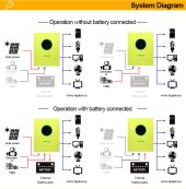
operation_with_without_battery.jpeg

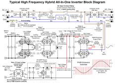
Regarding the mixing of AC and PV sources, we talk about it on this forum, there is a good chance that this AIO works like the diagram below.
And if this is the case then the mixing of AC and PV inputs is certainly not possible.

The "Stage 2 Sinewave PWM Converter" can work in both directions but not at the same time!

1) either "Stage 2" is used to produce the inverter AC signal " BAT or PV => HV DC => Stage 2 => inverter AC output "
2) either "Stage 2" is used to convert AC in to HV DC for battery charging "AC input => Stage 2 => HV DC => Stage 1 => Battery"

So to mix the AC and PV inputs the "Stage 2" is already used in the direction "PV input => HV DC => Stage 2 => inverter AC output" and cannot be used at the same time in the other direction.

The only solution would be to synchronize the inverter AC output signal with the AC input signal before sending it to the AC output. It is unlikely that this AIO can do that. This could also allow injecting on the Utility network.

Besides, if we look at the "System Diagram - Operation without battery" (above) the mixing seems impossible.

So before making an upgrade with a risk that it no longer works as expected, it is good to understand all this.

HF inverter block diagram.png
 
  • Like
Reactions: SuB
Does your AIO work well today with version 6.63 ?

Is firmware 6.63 a "without battery" version ?

Do you (or your friends) get an 03 alarm on the screen when the battery is disconnected ?

View attachment 135145
Yes we got the 03 error code without battery but the inverter started with the "batteryless" firmware. I will try ASAP with 6.63.

EDIT: it is not starting the output without battery, only displaying the error code and that's all.
 
Last edited:
I think there are two type of firmware, the regular firmware where it is necessary to connect a battery and the firmware without battery.

Frankly I do not know what brings the firmware without battery apart from not having an error when you do not connect a battery?

View attachment 135162

Regarding the mixing of AC and PV sources, we talk about it on this forum, there is a good chance that this AIO works like the diagram below.
And if this is the case then the mixing of AC and PV inputs is certainly not possible.

The "Stage 2 Sinewave PWM Converter" can work in both directions but not at the same time!

1) either "Stage 2" is used to produce the inverter AC signal " BAT or PV => HV DC => Stage 2 => inverter AC output "
2) either "Stage 2" is used to convert AC in to HV DC for battery charging "AC input => Stage 2 => HV DC => Stage 1 => Battery"

So to mix the AC and PV inputs the "Stage 2" is already used in the direction "PV input => HV DC => Stage 2 => inverter AC output" and cannot be used at the same time in the other direction.

The only solution would be to synchronize the inverter AC output signal with the AC input signal before sending it to the AC output. It is unlikely that this AIO can do that. This could also allow injecting on the Utility network.

Besides, if we look at the "System Diagram - Operation without battery" (above) the mixing seems impossible.

So before making an upgrade with a risk that it no longer works as expected, it is good to understand all this.

View attachment 135159
Do you have any service manuals or schematics? Mine still hasn't reporting PV input current correctly (stays zero, sometimes bumping up for a short period). I think it is a hardware problem.
 
Do you have any service manuals or schematics? Mine still hasn't reporting PV input current correctly (stays zero, sometimes bumping up for a short period). I think it is a hardware problem.

I have service manual only for Voltronic AIO.
 
My brand new SMX 3.6kW had a hardware fatal error. The small motherboard that is connected to the PV, is also connected parallel with + and - to the main motherboard. But that is not all. On the right upper corner there is another transversal stick, that also transmits "something". I have had a great deal of work to figure this out - mainly it was AC out on AC IN cables, when the inverter switch was on ON. Therefore my main circuitry switch on the house always went OFF when I start the inverter and it tries connect AC in.
When I isolated this upper right holder, the inverter begins to working as normal. I did get a replace main motherboard and it was designed the same way. I can provide some pictures if someone is interested.
Oh, and therefore this extreme buzzing when I turn on the inverter. After the isolation, inverter is quiet.
 
Last edited:
  • Like
Reactions: SuB
To explain a little further! I bought last year on the beginning of the year the EAsun Isolar-SMX-II 3.6kW model, because I did install another 4 230W 24V panels. Together I have had now 8 panels 230W 24V panels, connected in series (270V together) to inverter. I have had another 4 100Ah 12V sealed lead acid batteries connected in 2p2s that I got 200Ah at 24V.

Everything went fine until I first powered it on. I heard the fuse blow off and the main circuit breaker in the house went off. This was very strange since I have replaced another 3.6kW inverter for this one, which was working fine. Then I contacted the EAsun and I waited through whole summer that they send me the replacement main board.

I figured that when I connect the batteries and PV, everything is fine. Also if I connect the AC IN when the inverter switch is OFF, everything is fine. However, as soon as I flip the inverter switch to ON, and the inverter tries to pull the AC, the main circuit breaker went off in my house - which means grounding problems. I tried to measure what was comming out of the AC IN connectors and there was a few Watts of power, I did not measure at what voltage. I also measured that blue and yellow green had a contact.

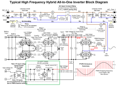
When I received the new mainboard, i replaced it first. On the first run, it happens the same, only this time the circuit breaker in the inverter did not go of, however my circuit breaker on the house went off. This was strange as this was completely new board. So I did some research and noticed under tha light, that the smaller PV board, which is mounted on top of the mainboard, is connected via the 3 sticks, where they transfer the PV-, PV- and one that transfers - I don't know why another PV+ to the casing via the upper right stick. This one was the only that was connected to the grounding of the case.

I do not know why did I try to isolate this one, however, the inverter stops buzzing and AC IN manage to stay on the line. I attach a picture, since the diagram is clearly NOT correct. There is another connection with the PV board, marked as green, to the casing of the case.

I have a version 6.61 and 2.01, and it does not run on the battery only, however, there is 03 message constantly on.
 

Attachments

  • HF inverter block diagram.png
    HF inverter block diagram.png
    773.6 KB · Views: 74
  • Like
Reactions: SuB
To explain a little further! I bought last year on the beginning of the year the EAsun Isolar-SMX-II 3.6kW model, because I did install another 4 230W 24V panels. Together I have had now 8 panels 230W 24V panels, connected in series (270V together) to inverter. I have had another 4 100Ah 12V sealed lead acid batteries connected in 2p2s that I got 200Ah at 24V.

Everything went fine until I first powered it on. I heard the fuse blow off and the main circuit breaker in the house went off. This was very strange since I have replaced another 3.6kW inverter for this one, which was working fine. Then I contacted the EAsun and I waited through whole summer that they send me the replacement main board.

I figured that when I connect the batteries and PV, everything is fine. Also if I connect the AC IN when the inverter switch is OFF, everything is fine. However, as soon as I flip the inverter switch to ON, and the inverter tries to pull the AC, the main circuit breaker went off in my house - which means grounding problems. I tried to measure what was comming out of the AC IN connectors and there was a few Watts of power, I did not measure at what voltage. I also measured that blue and yellow green had a contact.

When I received the new mainboard, i replaced it first. On the first run, it happens the same, only this time the circuit breaker in the inverter did not go of, however my circuit breaker on the house went off. This was strange as this was completely new board. So I did some research and noticed under tha light, that the smaller PV board, which is mounted on top of the mainboard, is connected via the 3 sticks, where they transfer the PV-, PV- and one that transfers - I don't know why another PV+ to the casing via the upper right stick. This one was the only that was connected to the grounding of the case.

I do not know why did I try to isolate this one, however, the inverter stops buzzing and AC IN manage to stay on the line. I attach a picture, since the diagram is clearly NOT correct. There is another connection with the PV board, marked as green, to the casing of the case.

I have a version 6.61 and 2.01, and it does not run on the battery only, however, there is 03 message constantly on.

Very interesting, I myself had a problem with my differential circuit breaker and my EAsun SMX II 5.6KW. I don't know how I managed to create this problem and it only happened once.
If the operator network (AC IN) is connected with the ground wire everything works fine but without the operator network and even if the ground remains connected then there is an ground problem.

As a reminder in off-grid mode without the AC IN network, it is necessary to connect the neutral to the ground via an external relay, according to my measurements our EAsun SMX does not do it automatically as in the diagram you have attached.

The voltage measured between neutral and ground should be 0V with or without AC IN connected.

It is normal to have the error 03 without battery, it is an inverter designed to operate with a battery. There is firmware for batteryless operation but until proven otherwise it is unable to mix PV and AC IN.
 
  • Like
Reactions: SuB
Back
Top