diy solar

diy solar

Differences in input between shunt and mppt controller

Ryang

New Member
Joined
Mar 18, 2020
Messages
210
Hi all

thanks for taking the time to read and help answer my questions.

I have what I think is a weird one.

I have noticed there is a substantial difference between the readings on my renogy rover 40 mppt and my battery monitor

i would of expected a loss perhaps, bit I have a gain.

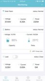
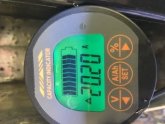
it’s about a 25% gain where the shunt is showing more amps coming in (and there is only the one input source) that’s the controller is showing going out.

I’ve always had a gut feeling the controller is giving inaccurate readings and this seems even stranger to me.

ive attached pics taken 2 seconds apart.
Can anyone help explain?

thanks
 

Attachments

  • DFAC6ABA-8B88-4D6A-864C-056602D92CDD.jpg
    DFAC6ABA-8B88-4D6A-864C-056602D92CDD.jpg
    14.6 KB · Views: 19
  • 4955A97B-AD42-4673-A198-7E220DD9CCA4.jpeg
    4955A97B-AD42-4673-A198-7E220DD9CCA4.jpeg
    27.8 KB · Views: 17
That does seem odd. One or both of the readings must be off. Do you have a clamp-on DC ammeter you can use to check what it thinks?
 
Not yet. I ha e one on order though. So about a week.

I have the 300amp shunt. Like in wills chargers video he has to calculate the resistance of the shunt. Could it be something like this?
 
I'm not entirely clear what that screenshot from your Rover is telling you but reading it from the top it seems like it's showing you the input voltage from the panel and the resulting wattage that it's generating.

The middle section is showing you the current capacity of the battery and it's voltage
In the bottom is showing consumption based on the loads

None of those are showing you the input amperage going to the battery

The battery meter is showing you the amperage going into the battery
 
Ignore that last post I downloaded that image to blow it up and I see that the current which is presumably the amperage going to the battery is 16? Is that meant to indicate 16 amps going to the battery?
 
Yes that’s how I read it. 16 amp gong in.
Battery meter showing 20
 
When the system is at rest check the voltage at the solar charge controller system side terminals.
Then the positive battery terminals and both sides of the shunt.
Record the values and report back.
Compare those to the SCC voltage indicator and the battery monitor.
 
I'd also ask that you take the reading from the screen on the rover vs a phone app (assuming that's where that screenshot came from)
 
Will do. Suns up so will have to wait until tonight.

what I can add, is that right now the solar reads 0amp going to for battery, butthe shunts shows a increase of 2.5amp. Really weird hey
 
Will do. Suns up so will have to wait until tonight.

what I can add, is that right now the solar reads 0amp going to for battery, butthe shunts shows a increase of 2.5amp. Really weird hey
You should have a disconnect between your panels and the solar charge controller.
 
Will do. Suns up so will have to wait until tonight.

what I can add, is that right now the solar reads 0amp going to for battery, butthe shunts shows a increase of 2.5amp. Really weird hey

My hall effect sensor shows in and out your shunt should behave similar.
It shows battery discharge as a positive number and battery charge as a negative.
If there is a load then the solar charge controller will share it and the number on the battery monitor would increase if the solar charge controller was helping out less.
In summary the battery is making up the difference.
 
I'd also ask that you take the reading from the screen on the rover vs a phone app (assuming that's where that screenshot came from)

these are the same. The screen and a
When the system is at rest check the voltage at the solar charge controller system side terminals.
Then the positive battery terminals and both sides of the shunt.
Record the values and report back.
Compare those to the SCC voltage indicator and the battery monitor.

Okay so the answers are
1. P.v @ SCC - 0.13
2. Battery positive @ SCC - 13.30
3. Battery voltage - 13.29
4. Shunt in - 13.29
5. Shunt out - 13.29
6. Shunt screen showing 13.30
7. Renogy SCC shows - 13.00
8. Renogy bt shows 13.00

Cheers
 
these are the same. The screen and a


Okay so the answers are
1. P.v @ SCC - 0.13
2. Battery positive @ SCC - 13.30
3. Battery voltage - 13.29
4. Shunt in - 13.29
5. Shunt out - 13.29
6. Shunt screen showing 13.30
7. Renogy SCC shows - 13.00
8. Renogy bt shows 13.00

Cheers

Ok so the shunt is probably accurate and the SCC is showing .3 volts low.
Did you consider my hyphothesis that the shunt is correctly showing you net flow?
 
Ok so the shunt is probably accurate and the SCC is showing .3 volts low.
Did you consider my hyphothesis that the shunt is correctly showing you net flow?

Yeah clearly the scc is down. My concern is that the scc has never seemed right (gut feel). I’ve got 800w of panels and never seen above 300w. The voltages are out (as per this thread?). I just don’t know if it’s internally got a fault and it’s working, but not correctly.

As per your hypothesis, honestly I didn’t quite understand it.
 
Shunt shows 20.20 amps going into the battery
SCC shows 16.25 amps going into the system
Either one or both of the scc + shunt are wrong.
Or... There is another charge source.
Or... you have the shunt in backwards and you actually have a 36.45 amp load.
The clamp meter should be informative.
 
There is definently not another charge source. We are totally off grid atm in the caravan so that’s not possible.

The shunt isn’t backwards I’m 100% sure.. though I do wish I had a 36.45 amp load. However the scc would show this and it doesn’t as would the battery capacity. Everything else seems normal in operation (use of batteries etc).

I would hypothesis if the SCC is showing .3v less at it’s own terminals something inside seems askew. Then further hypothesis that the function of mppt reading voltages, setting charge currents etc is not operating optimally.

That said I am just. A hacker trying to figure this all out so I really appreciate you all taking the time to provide input.

The .3v difference is likely just the resistance of the components(including wire) between the battery terminals and the scc terminals.
 
Except that at the scc terminals, it reads the same as the shunt. The .3 difference is between the scc’s terminals and the internals on the scc controller.
 
Except that at the scc terminals, it reads the same as the shunt. The .3 difference is between the scc’s terminals and the internals on the scc controller.

Ok everything agrees except the renogy about system voltage.
I would still wait for the clamp meter regarding the current dispartity.
Maybe a talk with Renogy tech support will be in order after you test with the clamp meter.
 

diy solar

diy solar
Back
Top