diy solar

diy solar

[JK BMS] cutting down on balancing wires?

fRzzy

New Member
Joined
Mar 23, 2023
Messages
4
Location
VN
Hello, I'm trying to build my first pack with 8 LFP cells using JK 8-17S BMS...

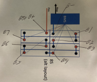
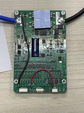
In order to remove unnecessary balancing wires, I want to solder the black wire directly to the B- terminal and the last red wire to the B8+ wire. There will be only 8 wires coming out of the BMS to the cells.

I don't see any (potential) problems doing this, but I want to make sure, is there any problem if I do this?

Thank you!
 
Another question, from the manual it says that the BMS power requirement is 20-100V, does that mean the last red wire doesn't really need to connect to the last cell positive pole? I figure if I want to rebuild the pack to 16S I can just add 8 more wires to the balancing port to connect to the added cells, and leave the last red wire connect to the B8+ pin.
 
In order to remove unnecessary balancing wires, I want to solder the black wire directly to the B- terminal and the last red wire to the B8+ wire. There will be only 8 wires coming out of the BMS to the cells.

What am, I missing? How does that remove "unnecessary" wires? And how are they unnecessary?
 
You need 10 wires. Yes you could splice that black wire into neg bat lead and the most pos into 8+, but you still have 10 wires being used out of the connector. I usually cut all other unused wires at 1.5” and cover with heat shrink for possible future use. I sometimes cut them off flush on my 16S, because I know I’ll never need 17-24.
 
What am, I missing? How does that remove "unnecessary" wires? And how are they unnecessary?
uhmm the BMS support 17S and I only have 8S, there are 9 wires that aren't connected to anywhere, aren't they unnecessary? or should I say "unused"?
You need 10 wires. Yes you could splice that black wire into neg bat lead and the most pos into 8+, but you still have 10 wires being used out of the connector. I usually cut all other unused wires at 1.5” and cover with heat shrink for possible future use. I sometimes cut them off flush on my 16S, because I know I’ll never need 17-24.
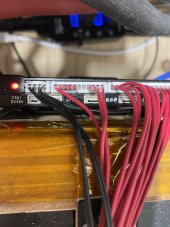
I have already taken out unused wires by removing the terminal out of the connector, that way they are still intact and I can reuse them later as needed.

About the negative wire and the last positive wire (for the BMS power supply) I'm thinking about solder directly to the connector pin on the PCB, no wire needed.

I think no bad thing going to happen, I'll do it tomorrow and update the result with pic if you want.
 
You might find this helpful

 
uhmm the BMS support 17S and I only have 8S, there are 9 wires that aren't connected to anywhere, aren't they unnecessary? or should I say "unused"?

I have already taken out unused wires by removing the terminal out of the connector, that way they are still intact and I can reuse them later as needed.

About the negative wire and the last positive wire (for the BMS power supply) I'm thinking about solder directly to the connector pin on the PCB, no wire needed.

I think no bad thing going to happen, I'll do it tomorrow and update the result with pic if you want.
Yeah, let us know. Thank you.
 
uhmm the BMS support 17S and I only have 8S, there are 9 wires that aren't connected to anywhere, aren't they unnecessary? or should I say "unused"?

Your post sounded like you were trying to eliminate some of the ones you needed. So just remove the extras like you said you did - problem solved.
 
If I want to disconnect power to the BMS, I pull the connector. No tools needed. If you want to, you’ll need to either disconnect BMS red wire at positive terminal on Cell 8 or B- cable from Cell 1. That is the only difference I can think of.
 
The only issue I see is that the cell 8 + won't see the same resistance as the others. Which could throw off the balancing. But if you are only talking about the power wire. I guess it shouldn't matter.
 
You might get some Voltage readings that are a little off on cell #1 under load because there’s some resistance between the B- terminal and the negative terminal of battery 1.
I doubt it would make a big difference except under large currents, but that difference is presumably the reason why there’s a separate lead rather than the BMS just measuring cell 1 voltage off the B- connection.
 
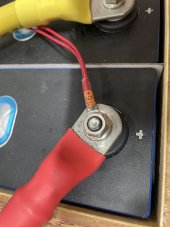
Like others have said. You may see a bit of balance issues with pairing into one lead. The last wire (power, positive) has the load of running the bms like the black. However, the black probably is compensated for since it does triple duty of power, sense and balance. The positive can’t be compensated because they have no idea how many cells you will run so hence, the extra lead. Probably the only place I’d share the last of string and the power is in the terminal as pictured. You can cut the leads you don’t need and Shoe Goop the ends. You can also remove a few by pushing the retaining barb down and pull the wire out. Don’t remove more than a few and only in the middle of the plug because they are needed to keep it in the bms. I like to pull a few for spares and in case I cut one too short, I’ve got a do over. You can cut the length of the leads as short as you need, that won’t make a difference. 8D8D8952-7091-4AE7-92B0-8921289F758E.jpeg4344805C-6D92-4719-8B91-2ED648D1BD41.jpeg522136F4-C3D1-447F-99C7-1F4BA6074C33.jpeg
 
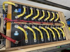
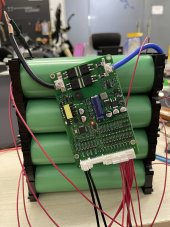
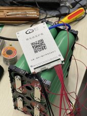
Hello, I did what I planned to do and no magic smoke yet (yay)

I haven’t fully assembled the pack yet, still waiting on the enclosure.

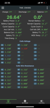
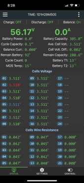
First cell wire resistance seems to lower than the others, not sure if it’s because of the shorter ground wire?2F083885-287B-4F5E-8C4D-F97C9A2E88C9.jpegABB5C334-CE5D-42BC-9959-F09EAE4E76FE.jpeg5ED15D52-4D34-41DE-B96A-84CA8F951516.pngimage.jpg
 
Shorter wire can be a factor. If you still have some unused spares you can switch it out to verify.
 
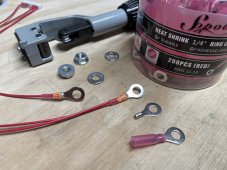
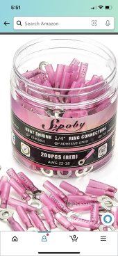
Here’s an old screenshot, the bottom is cut off so it doesn’t show all cells and I’m not at home to get another. There’s a big resistance difference from yours. Battery chemistry involved? I highly recommend this brand of ring terminals. They are much harder than normal and don’t mush away. They are plated brass. You strip twice as normal, fold insert and crimp with an MC4 crimper. Flip the jaw so the crimp selected is closest to the hinge. After crimping put dab of solder over the end to keep moisture out the use adhesive heat shrink to seal the deal.BA8D6E90-7520-4DA5-A9C5-2F7931FC52FC.jpeg262A8D4F-5677-4331-86DF-86AD76A13CBC.jpeg849C4F2F-7A59-4FAC-A1A7-079129B9B03E.png
 
Back
Top