diy solar

diy solar

Hacking DC supply into DC inverter mini split.

Should I open one up, post pics and have you guys tell me where to tie in the panels and such?
I have good soldering skills, just no knowledge of where to perform the surgery.
 
Should I open one up, post pics and have you guys tell me where to tie in the panels and such?
I have good soldering skills, just no knowledge of where to perform the surgery.
Yeah post em if you're interested to. You can see the pictures earlier in this thread when we worked on finding mine.
 
I'm noticing now this mrcool 27k 3 zone unit is drawing .8 amps with all the heads turned off... That's $40/month for me just in standby.
 
I'm reading that this standby consumption is probably coming from the crankcase heater. I already disconnected my pan heater I think I'll disconnect this too. We only get down to 23 in winter and the heat pump is running on those nights.
 
Rough power consumption on compressor is about 800-900 watts per 12,000 btu (1 ton) unit btu rating. That is when running at full output loading.

Most of the 240vac mini-splits have some amount of power factor correction. An active power factor correction module has a DC output of about 360 vdc to run the three phase inverter for variable speed compressor.

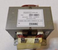
Many units in U.S. only have an inductor choke between rectifier and filter capacitor and have a DC output of 310 to 330 vdc. That only improves PF from about 0.6-0.65 to 0.75-0.80.
Mini Split AC PF choke.png

The HV DC bus on 240vac only HF inverters is about the correct DC voltage. You need to be sure there is not something like relays or fans that run directly on AC input source. In many reverse cycle units, the reversing valve runs on 240 vac solenoid..
 

Attachments

  • 500 to 1500W Power Factor Correction Modules.pdf
    391.9 KB · Views: 3
I would not worry too much about feeding dc back into the grid.
Yes, I know it is bad, and the utilities hate it, but many appliances such as heat guns and hair dryers use a diode in series with the heating element for "low heat" setting.
I suppose if you have a dozen hair dryers all running on low heat, the connection phasing will be random anyway and it should likely balance out, which I suppose why such appliances are still tolerated.
 
Disconnecting the crankcase heater did not change my .8 amp standby draw. Could this be one of those situations where it's like only 20 watts but shows up as .8 amps because of terrible power factor?
 
I would not worry too much about feeding dc back into the grid.
Yes, I know it is bad, and the utilities hate it, but many appliances such as heat guns and hair dryers use a diode in series with the heating element for "low heat" setting.
I suppose if you have a dozen hair dryers all running on low heat, the connection phasing will be random anyway and it should likely balance out, which I suppose why such appliances are still tolerated.

Still not a problem.
The problem is putting about 1% of transformer rated current through its windings as DC. That will saturate it, causing inductance to drop precipitously. And then their grid AC will shoot excessive current through it and burn it up.

Should I open one up, post pics and have you guys tell me where to tie in the panels and such?
I have good soldering skills, just no knowledge of where to perform the surgery.

I suggesting starting with capacitor and diode part numbers and specs. That will show what they can handle reliably, as opposed to what fails immediately.

I'm thinking many devices can operate from 208V to 250V, so Vmp and Voc might be OK while staying below Vpp of normal AC source.
 
Do they have working compressors and EEV? Or you are keeping the good parts.
They are pulls that I replaced with new units.
System leakers, acid buildup from poorly installed systems. That kind of thing.
Scrap value only.
Happy to demolish them for a cause.
 
They are pulls that I replaced with new units.
System leakers, acid buildup from poorly installed systems. That kind of thing.
Scrap value only.
Happy to demolish them for a cause.
Hmm, could you spin one up (without refrigerant) to test injecting DC into post rectifier HV DC bus? But it sounds like a lot of work for not much reward.
What do you think of Everwell and Daizuki brand mini splits? They sell them here in South FL for $600 for 12k BTU 20 seer. They have variable speed compressors but use capillary tubes. I want the one with EEV but the cheapest Pioneer EEV unit is $1000.
 
Maybe they are not regulating. Looking at the manual I don't see MPPT mentioned anywhere. DC input range is 90-380V which could mean that PV is directly tied to DC bus and regulation could be done via compressor inverter speed control acting as backwards MPPT.
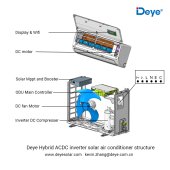
Fyi, Your first assumption was 100% correct WRT to Deye and MPPT Booster:
Structure.jpg
 
Ah, no. It works for assist.

I don't know if my array is just inadequate but I do believe the indoor units don't run off the DC bus and therefore don't run without the AC supply.

Makes sense. Controls may have transformer, may have switch mode supply. If switch-mode, could also be powered by DC (either direct to DC bus as you did for compressor, or through its AC leads.) If through transformer you'd need to substituted switch-mode supply

Existing fans likely AC motors, substitutes could also be powered by DC/DC but wouldn't fit nicely.

If you determine that 100% of the device is powered by SMPS and switch-mode supply, all having rectifier/capacitor front end (no AC motors), in that case the entire unit could be powered by DC.

To feed from both AC and DC, you could get a bank of 6 diodes (3-phase rectifier), and wire as single-phase full wave rectifier (for AC input) plus pair of blocking diodes (for PV DC input).

We have fed SMPS from DC. Even though they were power-factor corrected, they worked with straight DC.
 
Most of my electricity gets used for AC and/or heating. I've wanted to work out something where I tap the HV DC bus inside the inverter and use it directly in a programmable variable frequency drive for a refrigeration loop compressor - to generate both hot and chilled water for HVAC and DHW. It would cut out a couple power conversion stages. There are a few ways I could coordinate it.

There have been and now more mini-splits that match (or use) the VFD at MPPT. I want a small system that will make as much hot water and cold water to respective temperature limits as an energy storage mechanism. I think there would be a market for that too.

 
Last edited:
I left the 10 panel array (450 VOC) plugged in overnight by accident and in the early morning when the compressor was cycling on and completely off, maybe 50 degrees outside, I started getting IPM voltage errors.

This I think finally concluded my experiment and confirms that it is tricky to balance the voltage range of the raw panel output to align with above 340v and under 450v.
 

diy solar

diy solar
Back
Top