diy solar

diy solar

24V Electric micro-campervan single panel setup

Daavok

New Member
Joined
Dec 29, 2019
Messages
10
Hi gang,
I wanted to double check with your far more knowlegeable eyes this set up I want to build for my Nissan e-nv200 camper van.
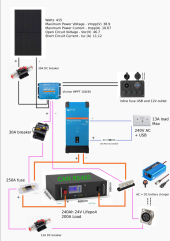
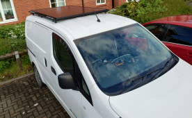
It is centered around this large rack battery and a single 415W panel taking up the entire roof section of this small van.
I have only mounted the panel now and gathered the main components of the buil;d such as the inverter and the mppt.

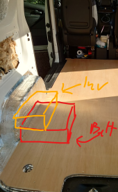
NB: the inverter will need to be mounted above the battery due to space constraints. It will be seperated by a non flammable board and encased in a heat tolerant wooden box.

So yeah, does this seem ok?
 

Attachments

  • circuit Diagram RV power system.png
    circuit Diagram RV power system.png
    349.2 KB · Views: 22
  • solarMount.png
    solarMount.png
    1.9 MB · Views: 21
  • Screenshot 2023-06-07 102108.png
    Screenshot 2023-06-07 102108.png
    679 KB · Views: 21
Looking good!

Three things:

Those 30amp DC breakers are rubbish I wouldn't trust them , you're better off with a midi fuse, in fact all the dc breakers in your photo aren't very good, they are ok to use as a DC switch, but they don't always trip when you need them to... Fuses or quality breakers are the best two options

I see you've got an RCD on the 240vac side, great, but you also need some kind of MCB/AC fuse (unless that's already in the victron inverter??) Or perhaps an RCBO which serves both functions

Also you've not listed cable sizes , that's simple enough to work out but must be done connectly


Screenshot_2023-06-07-12-35-36-251-edit_com.android.chrome.jpg
 
The inverter as well as the MPPT need air flow to stay cool.

I don't know if the Victron 100/20 is less expensive than the 100/30. With that panel you're not likely to exceed 20 amps, so the 100/20 is sized better.

Your diagram has a USB port coming off of the 100/30. That model does not have a load output. The 100/20 does.

I recommend using a good quality bus bar for both the positive and negative. It can make your wiring easier.
 
Looking good!

Three things:

Those 30amp DC breakers are rubbish I wouldn't trust them , you're better off with a midi fuse, in fact all the dc breakers in your photo aren't very good, they are ok to use as a DC switch, but they don't always trip when you need them to... Fuses or quality breakers are the best two options

I see you've got an RCD on the 240vac side, great, but you also need some kind of MCB/AC fuse (unless that's already in the victron inverter??) Or perhaps an RCBO which serves both functions

Also you've not listed cable sizes , that's simple enough to work out but must be done connectly


View attachment 152029

Thanks for those details. I know those breakers are bad, I wonder if you could point me towards a good quality breaker? (also in the UK)
I rather have them as breakers instead of fuse for easy isolation of the various parts of the system.

Ah right, yes the cable size I forgot to mention:

Orange - 70mm
Black - 4mm
purple - 4mm too probably or larger depending on the size of the spare wire I have (don't have it on hand atm)
Blue - standard house AC cable, dunno what the size is but its good spec
 
The inverter as well as the MPPT need air flow to stay cool.

I don't know if the Victron 100/20 is less expensive than the 100/30. With that panel you're not likely to exceed 20 amps, so the 100/20 is sized better.

Your diagram has a USB port coming off of the 100/30. That model does not have a load output. The 100/20 does.

I recommend using a good quality bus bar for both the positive and negative. It can make your wiring easier.
Well spotted. I actually ended up getting the 100|20
I shall go for victron bus bar for both ends.
 
Thanks for those details. I know those breakers are bad, I wonder if you could point me towards a good quality breaker? (also in the UK)
I rather have them as breakers instead of fuse for easy isolation of the various parts of the system.

Ah right, yes the cable size I forgot to mention:

Orange - 70mm
Black - 4mm
purple - 4mm too probably or larger depending on the size of the spare wire I have (don't have it on hand atm)
Blue - standard house AC cable, dunno what the size is but its good spec

Quality DC rates breakers are few and far between I'm afraid!

Personally I go fuse and isolator separately


A lot of people use those DC breakers as a DC switch, pick a rating a lot higher than you need , then use a separate fuse to protect the wire
 
Last edited:
Orange - 70mm

That's big cable are you sure it's needed ? Not sure on the size or voltage of your inverter


Also are you going to charge the habitation battery from the van engine? Can be a real bonus in cloudy weather
 
It's not easy to get quality breakers in the UK at resionable cost, junk the rubbish breakers shown, they are a fire risk, and fit fuses.

To comply with UK regulations for 230v AC permanent install, ( and for your safety), you need earth leakage protection on the inverter output. This needs a double pole RCD, over current protection is optional, the inverter has internal current limit .


The inverter needs to be configured neutral to earth bond and the case earth connected to van metal. The AC distribution protective earth also to van metal.

The inline fuse and switch panel shown for DC is unsafe. Use a fuse box, 6 or 12 way,


And rewire the switches in the panel correctly, as supplied its a safety risk.

With the 415 panel you need the 100/30 , a 20 amp unit will run too hot given your limited space.

What power is the inverter, need to know for fuse and wire size?

Suggest a master fuse at the battery, MRBF or HRC type feeding a positive buss bar. At the buss bar fit midi/mega link fuses in fuseholders to feed the DC fuse box and solar controller,

You may wish to consider engine charging,

And battery monitoring,

Note shown 12v planet links for illustration, I have no connection to the company , parts available from other suppliers.
Avoid low cost fuses and breakers on ebay and Amazon.

Mike
 
Last edited:
Hi - what is the connector type in the bottom right of your picture ? I am not familiar with it. Thank you.
 
Quality DC rates breakers are few and far between I'm afraid!

Personally I go fuse and isolator separately


A lot of people use those DC isolators as a DC switch, pick a rating a lot higher than you need , then use a separate fuse to protect the wire
hmm, yeah I could do that. Cant seem to find a better option that is decently priced.
 
Hi - what is the connector type in the bottom right of your picture ? I am not familiar with it. Thank you.
Its an XLR plug. More often used for stage microphones, seems to be the default in these 24v power supplies.
 
That's big cable are you sure it's needed ? Not sure on the size or voltage of your inverter


Also are you going to charge the habitation battery from the van engine? Can be a real bonus in cloudy weather
The cable is sized up, probably unecessarily, just what I had available (lower was out of stock). Inverter is rated for 3000VA @24V
I am not going to charge from the engine, it is an electric van. The onboard inverter supplying the 12V DC battery is only 2KW, although possible, to get the wiring in would be a pain.
 
I don't know if you have access to these DC breakers, but they are fairly high quality and worth using when feasible.

The traditional method of protecting the wire was to use a fuse. In order to change the fuse, you have to be able to turn off the power - so that is the purpose of the isolator switch.

A good quality, marine rated breaker can (often ) substitute for both. The nice thing is that you don't need tools or spare parts to re-set.


We can get the knock off versions in the UK
 
The cable is sized up, probably unecessarily, just what I had available (lower was out of stock). Inverter is rated for 3000VA @24V
I am not going to charge from the engine, it is an electric van. The onboard inverter supplying the 12V DC battery is only 2KW, although possible, to get the wiring in would be a pain.

Cool electric van , same technology as the nissan leaf if I'm not mistaken?


3000va @ 24v = 125amps

But really you need to calculate off the lowest voltage your battery could see so roughly:

3000va @ 21v = 142amps

So you could use 25mm² cable , rated for 170 amps , or if it's a really long run 35mm² to combat voltage drop


70mm² is literally double what you need , can be a real pain in the arse to work with especially round a little van . Also might well not fit in the terminals in your inverter, fuses, breakers, etc etc...

But up to you obviously!
 
I am not going to charge from the engine, it is an electric van. The onboard inverter supplying the 12V DC battery is only 2KW, although possible, to get the wiring in would be a pain.


All you have to do is hook a 12v inverter to the 12v auxiliary battery, but like you said it's 2kw max

And that's all well and good , but A) you have to have the engine turned on for it to charge , and B) you wouldn't be able to charge either the main traction battery or the aux 12v battery from solar , (at least not easily)
 
The switch panel is not correctly wired. The individual outputs are fused at 15 amps with inline fuses, 5 outlets total 75 amps.
The 12v car type outlet is unfused as the USB and voltmeter.
Overlooking the fact that the 12v outlet is not fused, the possible total current is 75 for the switched outlets plus a possible 10 amps for the car outlet, that's 85 amps. This is supplied by two undersized feed wires, everything on the panel is wired in series. The result, best case, is that volt drops effect 12v appliances, worst case overheating and fire.

This unit is intended to be connected to a 12v supply, at a minimum it needs a 10 amp fuse in the supply cable.

This is impractical and would limit the current available from the switches.

The ideal option is to use an additional fuse box and feed each switch with a fused positive, the fuse would be suitable for the cable and load, for example a led light would need a 5 amp fuse and 1mm2 cable, a compressor fridge 15 amp fuse and 6mm2 cable.
The negative being taken to the fusebox common negative. The inline fuses/holders are discarded, ( low cost not reliable).
Feed the 12v outlet with 2mm2 cable and a 10 amp fuse. Feed the USB and meter, wired in parallel with a 5 amp fuse and 1mm2 cable.

The panel is only useful for the parts and need a rewire as suggested.
 

Attachments

  • Screenshot_20230609-120302_Chrome.jpg
    Screenshot_20230609-120302_Chrome.jpg
    496 KB · Views: 3
There are USB ports that can run on dual 12 / 24 volt if that helps.

That way all that is needed is a fused connection to the 24 volt supply.

Very often they are superior to the 12 volt versions because they enable higher output capability for charging devices that designed to handle it.

A number of companies sell them. In the US I know of powerex, blue sea, and there are many other brands on line. Very common in marine stores.
 
I am curious about something with the breaker / fuse requirement between the inverter and the AC outlet.

With low power inverters like that - and only getting modest power from the battery - is a breaker even needed between the inverter and final outlet ?

Isn't there self protection built into the inverter?
 
forgot to add to my post about the 12v switch panel, assuming this is for 12v appliances
This cannot be connected to the 24v battery directly or the load terminals of the solar charger, a 24 to 12 volt converter is needed. example 10 amp umit , higher current version available
breaker even needed between the inverter and final outlet ?

Isn't there self protection built into the inverter?
a fault in the inverter or short circuit on the feed cable, could cause excessive current to flow, (assume the battery BMS fails to protect), cable insulation melts and smoke and fire.
Above 100 amps the volt drop across a breaker is higher than a fuse.
 
I just use 24 volt appliances in vans and skip 12 volt ones to the extent possible.

Refrigerators, fans, LED light strips, USB ports, diesel or gas heaters, pretty much all come in 24 volt models so it is rare to need a DC converter except perhaps for an exhaust fan. The boating / marine industry is a great resource for 24 volt stuff.

The marine fuse panels are nearly all rated for 24 volt use and can often take in a 100 amp feed from a breaker.

They sell for less than $100 in the US for high quality ones.

If you are paying a lot more than that for cheap ones in the UK, maybe someone should help you set up an import business.
 
The switch panel is not correctly wired. The individual outputs are fused at 15 amps with inline fuses, 5 outlets total 75 amps.
The 12v car type outlet is unfused as the USB and voltmeter.
Overlooking the fact that the 12v outlet is not fused, the possible total current is 75 for the switched outlets plus a possible 10 amps for the car outlet, that's 85 amps. This is supplied by two undersized feed wires, everything on the panel is wired in series. The result, best case, is that volt drops effect 12v appliances, worst case overheating and fire.

This unit is intended to be connected to a 12v supply, at a minimum it needs a 10 amp fuse in the supply cable.

This is impractical and would limit the current available from the switches.

The ideal option is to use an additional fuse box and feed each switch with a fused positive, the fuse would be suitable for the cable and load, for example a led light would need a 5 amp fuse and 1mm2 cable, a compressor fridge 15 amp fuse and 6mm2 cable.
The negative being taken to the fusebox common negative. The inline fuses/holders are discarded, ( low cost not reliable).
Feed the 12v outlet with 2mm2 cable and a 10 amp fuse. Feed the USB and meter, wired in parallel with a 5 amp fuse and 1mm2 cable.

The panel is only useful for the parts and need a rewire as suggested.
Right I see, thank you. I shall do that, don't mind the extra setup, just thought this would be tiddier.
 

diy solar

diy solar
Back
Top