diy solar

diy solar

Measuring Battery Resistance

chrisski

Solar Boondocker
Joined
Aug 14, 2020
Messages
5,471
Any tips for measuring Battery resistance? Device? Only when top balanced or should this even matter"

I have a battery capacity tester that gives me a reading, but can quickly climb as the test goes on. I have the topband 25 ah lithium cells from battery hookup. When I hook my DL-24P capacity tester to these batteries after top balancing, the batteries measure 3 mΩ or 4 mΩ, which matches what is advertised. Almost immediately resistance will rise to 5 mΩ and within minutes be 17 mΩ and over the course of a 5 amp 5 hour discharge cycle will rises as high as 50mΩ

I'm trying to match my batteries as much as possible, and don't know what the standard is since I expected resistance to be the same.
 
There are tools for that, don't have one and never used one though. Considering their chemical reactions depending on ion flow I'm not surprised resistance changes with use, but I'd expect them to change at the same rate.

I don't know much about it, but there are some threads on it (e.g., https://diysolarforum.com/threads/diy-cell-matching-process.16784/)
 
Most of what people call cell resistance in this forum and stated by vendors is 1KHz AC, very low drive, impedance tester, like YR1035+ tester. It is partially ohmic resistance due to terminal interconnect, metal foil current collector resistance and partially ionic diffusion resistance through cell. It amounts to 5% to 30% of the net terminal voltage drop with cell current depending on level of cell current. It is one indication of cell performance and matching but not the only parameter that should to be examined.

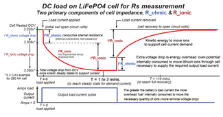
The three dominate components causing cell terminal voltage drop (or rise during charging) is direct conductor loss, ionic transfer, and overpotential. Overpotential times cell current is energy used to create and transfer lithium ions necessary to support cell current demand. To make things more complicated, the overpotential and ion movement has a time response delay in reaction to cell current change.

When you measure resistance with a load tester you are measuring initial immediate ohmic conduction voltage drop, from rested no load cell voltage, followed by an additional exponential decay due to ionic and overpotential decay ramp. This can take a couple of minutes to reach equilibrium and depends on cell current and where in the state of charge the cell is. To repeat measurement you must allow time for cell to return back to equilibrium for no load current. An AC 1kHz impedance tester creates no net overpotential terminal voltage change and has no time decay in the measurment. It will be greater in the upper 15% and lower 20% of cell state of charge level.

Ionic transfer resistance changes with state of charge, getting greater when ions get scarce near full charging or near fully discharged. The overpotential must get greater to drive the scarce ions, explaining why terminal voltage drops quickly near full discharge and terminal voltage rises near full charge. Temperature is also a very big factor particularly below +10 degs C. As cells get old their ability to move ions through the cell has more resistance.

Rs and Kinetic voltage drop measurement.png
 
Last edited:
Most of what people call cell resistance in this forum and stated by vendors is 1KHz AC, very low drive, impedance tester, like YR1035+ tester.

I have one of these and two of the preceding YR1030. My only complaint is accuracy. All three read different values on the same cell, and their calibration is only somewhat effective. If I stick with a single instrument, it is highly repeatable, and I regard it as very valuable for comparison, i.e., if two cells measure the same resistance, they're the same... even if the value is off.

When you measure resistance with a load tester you are measuring initial immediate ohmic conduction voltage drop, from rested no load cell voltage, followed by an additional exponential decay due to ionic and overpotential decay ramp. This can take a couple of minutes to reach equilibrium and depends on cell current and where in the state of charge the cell is. To repeat measurement you must allow time for cell to return back to equilibrium for no load current. An AC 1kHz impedance tester creates no net overpotential terminal voltage change and has no time decay in the measurment. It will be greater in the upper 15% and lower 20% of cell state of charge level.

If you use the voltage difference between two loads, is it closer to an actual resistance, i.e., if I start with a 10A load hold it for several seconds until the voltage stabilizes, then hit it with a 20A load for several seconds observing the voltage drop? I like to also go back and forth to establish the same voltage difference when current is stepped, i.e., an A-B-A-B-A test... averaging the voltage drops/increases with each change in current and then divide by 10A to get Ω.

Does this yield meaningful results?
 
Last edited:
I have a YR1030 (older model) and it is not that accurate but not far off in general. I then got a YR1035+ Tester and it is much more accurate & logging features etc (that helps when doing lots of cells). For the average "non-scientist" purposes the YAOREA (OEM) YR1035+ is reasonably good and can be had for <$50 USD.
 
Overpotential voltage mostly represents the electromotive force for migration of lithium-ion molecules through the electrolyte. It is not really a resistance but does create a cell terminal voltage drop during discharge or terminal voltage rise during charging.

The actual overpotential voltage for moderate cell current is usually much greater than the voltage drop due to cell ohmic resistance times cell DC current. Only ohmic resistance of a cell is what is being measured with a 1kHz cell impedance meter.

The YR1035+ only puts out a 1kHz AC current of about 50 mA rms. There is a narrow bandwidth 1 kHz filter in voltmeter to improve the signal to noise ratio to allow voltmeter to measure very low AC voltage levels. A 0.2 milliohm resistance driven with 50 mA of AC current only produces 10 microvolts of AC voltage that must be accurately measured. This voltage level is about 100 times lower than a TV channel signal level received on an outdoor TV antenna.

The 1 kHz AC signal of a battery impedance meter has almost no effect on creating electrolyte overpotential voltage as there is no DC current involved in the measurement.

Electrolyte acts as a fluid conductor of lithium ions. The fluid electrolyte soaks both electrodes, wrapping an ion conductive blanket around the granules of LFP and graphite in the positive and negative electrodes, respectively.

Electrolyte is a salt dissolved in a solvent. For most lithium-ion batteries, the salt is lithium hexafluorophosphate (LiPF6). When the salt is dissolved in solvent it disassociates into Li+ ions and PF6- cat-ions. The Li+ ions in electrolyte are the 'conveyor belt' for lithium-ion exchange between positive cathode LFP electrode and negative anode graphite electrode.

The electrolyte needs to remain neutral in charge as much as possible (same number of ions and cat-ions) or there can be chemical decomposition of electrolyte. Li+ ions are very chemically reactive and any free electrons that get into the electrolyte will bond with Li+ ion making lithium metal that makes the lithium inert to further battery operation (cell loses capacity). Normal (desired) cell operation is cell terminal electron flow stays restricted to LFP and graphite electrodes. Only lithium-ions flow, or more precisely, 'migrate' through electrolyte. One electrode gives an extra Li+ ion to electrolyte, making electrolyte temporarily positively charged, and other electrode absorbs a Li+ ion to re-establish electrolyte neutrality of charge.

Li+ ions migrate slowly in electrolyte, compared to electron flow in electrodes. This creates a time delay in establishing an equilibrium in the electrolyte for a given DC cell current demand.

You can think of electrolyte like ground water soaked in soil around a water well. As the well head sucks water from soil around well head (the electrode) it creates a local depletion of water soaked in soil. It takes some time for surrounding ground water to infiltrate soil to replenish the water/soil concentration around well head.

When you have high cell current it creates a local lithium-ion depletion around the ion receiving electrode and a bunch up of lithium-ions at the lithium-ion contributing electrode. This increases the overpotential voltage gradient in electrolyte necessary to push the required rate of lithium-ion migration through electrolyte. This increases the likelihood of a lithium-ion to getting nailed by a free electron. Eventually, within one to three minutes, a cell will reach an equilibrium state where the overpotential is a fixed value for a given amount of cell current necessary to maintain the cell current.

Measuring this overpotential at moderate cell current, 0.2 to 0.4 C(A), is a good method to evaluate cell health. Just measuring cell ohmic resistance with a 1 kHz battery impedance meter is not a great indicator of cell health as it does not evaluate ion migration very well, although it will increase a bit as cell ages. The overpotential voltage, however, will increase 3x to 5x over the lifetime of cell. Eventually, the cell will have too much voltage slump for moderate current demand making the cell unusable, tripping an inverter low battery voltage cutoff with heavy load on inverter.

Overpotential slump with load current.png

Li-Ion Graphite battery model.png
 
Last edited:

diy solar

diy solar
Back
Top