diy solar

diy solar

100amp sub panel Wire Size

I have done something along these lines many times to get out of recessed panels.
I believe your maximum allowable difference in depth is 6" before it becomes an obstruction to working clearance.
I did offset bend on two 3/4" conduits to jump into a few junction boxes and surface conduits when I installed a new recess panel and wanted expandability. I think I would have ended up being happier with sinking in a wireway underneath (but mind you I only had 1 month of seriouis wiring experience at that time and didn't think to do it this way). There was romex from the original house build stapled on the surrounding studs, so would need to work around that. I think the way to do that is to open up enough drywall to get a clear view of the stapled romex. Carefully frame in some 1x or 2x blocking (potentially removing some Romex staples to move the cables out of the way) and mount the wireway to that.
 
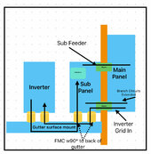
Forgive the crappy graphic but I think this will be compliant with a 6x6 x60” gutter (room for growth), note a common neutral design. Damn flush mount panels.

Two nipples between main and sub, one will have extended branch circuits and power to inverter grid IN passing through sub panel (not terminating there), other will have sub panel feeder.

Two FMC with 90° into back of UL 6x6 gutter through back of drywall from bottom of sub panel.

Can change this to a double throw easily vs interlock. All this is based on the ability to use subpanel as a jbox/pull point for inverter grid in.

Due to spacing, no way I could put the gutter under the main panel and try to get wire into it.
Thoughts?
IMG_5463.jpeg
 
Two FMC with 90° into back of UL 6x6
Section 348, Flexible Metal Conduit
348.42 Couplings and Connectors: Angle connectors shall not be concealed.
Try using 2- 6x6x4 boxes with a nipple into the bottom of the flush panel. Cut out the back of the gutter to match the openings of the boxes, drill holes to line up with the cover screws and pull them together. Cover the metal lip with that black edging they use on the edge of car doors.
You will thank me later if you ever need to pull more wire through there.
 
Forgive the crappy graphic but I think this will be compliant with a 6x6 x60” gutter (room for growth), note a common neutral design. Damn flush mount panels.

Two nipples between main and sub, one will have extended branch circuits and power to inverter grid IN passing through sub panel (not terminating there), other will have sub panel feeder.

Two FMC with 90° into back of UL 6x6 gutter through back of drywall from bottom of sub panel.

Can change this to a double throw easily vs interlock. All this is based on the ability to use subpanel as a jbox/pull point for inverter grid in.

Due to spacing, no way I could put the gutter under the main panel and try to get wire into it.
Thinking about the critical dimensions and conduit fill, and what you can get into it.

Bigger FMC might have rough time having enough clearance in the wall to do 90 degrees and still follow the bend radius. This is why I suggested recessing a deeper gutter -- you only need to do an offset, not 90 degrees turn, and offset is easy to achieve. You could consider using a lot of small FMC to have smaller bend radius, in this case you need to figure out what the highest conduit fill you need is (which will be determined I guess by your largest circuit). I don't believe FMC is valid as EGC for most of the circuit ampacities in question, so you will have to pull EGC through each of those. Unless you have some FMC that have only small ampacity circuits in them.

Maybe it's legal to put a LB behind the gutter to give a tight 90, but I suspect they need to be accessible. (EDIT: post above this had the code reference saying that they do need to be accessible)

What is the biggest diameter conduit you are willing to feed between your 2x4" framing?

The SER will get you the most current through the stud.

I think you can pass conductors for same circuit through parallel non-ferrous conduits, combined with cutting the side of the metal boxes (subpanel and main) to break the loop for eddy currents. Probably not worth the complexity, but it is a code compliant option.

Is there a stud between inverter and subpanel? That will determine how easy or hard the recessed gutter would be.
 
If you look at the exception chart that was provided for residential services and feeders, it shows #4 is acceptable for a 100A feeder in a dwelling unit. I have sized my residential services and feeders from that chart my entire career without any issues.
The proper way to size THHN wire is to use the 60C chart for circuits less than 100A and the 75C chart for circuits 100A and greater where the terminals are rated for at least that high. The 90C column is ONLY EVER used as the starting point for a full derating calculation. This is not made clear in section 314 but the NEC workbook shows it.
Some jurisdictions are more strict than NEC, and some electricians either don't know about the residential allowance table or choose not to use it.

You can put 3x 2/0 THHN and 1x #4 THHN in a 1.5" conduit and not be overfilled by NEC. It's not fun to pull however. I typically run 1" for 100A feeder of #4s, again not overfull.
And I am referring to conduit runs, not nipples.
Why would you use the 60C chart to size thhn for circuits less than 100 amps?
 
Why would you use the 60C chart to size thhn for circuits less than 100 amps?

Yeah that sounds kind of weird. I can buy that for THHN terminating in like cheap receptacles, I know some are 60C rated.

Breaker to breaker, you can use 75C

For terminals on the inverter, need to check the manual to see what temp it is. I can believe 60C for that. I would probably struggle with deciding whether to do 60C or 75C if the inverter manufacturer doesn't specify, especially if the lugs are limited in size of wire they accept.
 
Section 348, Flexible Metal Conduit
348.42 Couplings and Connectors: Angle connectors shall not be concealed.
Try using 2- 6x6x4 boxes with a nipple into the bottom of the flush panel. Cut out the back of the gutter to match the openings of the boxes, drill holes to line up with the cover screws and pull them together. Cover the metal lip with that black edging they use on the edge of car doors.
You will thank me later if you ever need to pull more wire through there.
@Snaketzu That’s brilliant. So some j-boxes nippled and recessed with sub panel and rear gutter cutout for those openings. Simple and can see the future advantage of it. Thank you.
 
Is there a stud between inverter and subpanel? That will determine how easy or hard the recessed gutter would be.
Yes studs are every 16” for this load bearing wall. Think the option above with recessed smaller j-boxes behind the surface mount gutter is the way to go.

If I ever move, can take the inverter and gutter with me and just put a blank plate over the recessed boxes.
 
Why would you use the 60C chart to size thhn for circuits less than 100 amps?
110.14(C)(1) The determination of termination provisions of equipment shall be based on 110.14(C)(1)(a) or (C)(1)(b). Unless the equipment is listed and marked otherwise, conductor ampacities shall be based on Table 310.16 as appropriately modified by 310.12.
(a) Termination provisions of equipment for circuits rated 100 amperes or less, or marked for 14AWG through 1AWG conductors, shall be used only for one of the following:
(1) Conductors rated 60C
(2) Conductors with higher temperature ratings, provided the ampacity of such conductors is based on the 60C ampacity of the conductor size used.
(3) Conductors with higher temperature ratings if the equipment is listed and identified for use with such conductors.
(4) For motors marked with design letters B, C, or D, conductors having an insulation rating of 75C or higher shall be permitted to be used, provided the ampacity of such conductors does not exceed the 75C ampacity.

So you can use the 75C chart for circuits less than 100A ONLY IF all of the terminations in the circuit are specifically rated for 75C.
This can be difficult to confirm.
In most cases, you are going to have at least one termination at an unspecified rating which forces the use of the 60C chart.
The NEC workbook shows this part of the wire sizing calculation clearly. You will notice that the 60C column in table 310.16 shows the way smaller circuits are typically wired, e.g. #14 at 15A, #12 at 20A, #10 at 30A, etc.
There is also the "tombstone rule" contained in another section.
240.4 Protection of Conductors. Conductors, other than flexible cords, flexible cables and fixture wires, shall be protected against overcurrent in accordance with their ampacities specified in 310.14, unless otherwise permitted or required in 240.4(A) through (G).
(D) Small conductors. Unless specifically permitted in 240.4(E) or (G), the overcurrent protection shall not exceed that required by (D)(1) through (D)(7) after any correction factors for ambient temperature and number of conductors have been applied.
(1) 18 AWG copper. 7 amperes
(2) 16 AWG copper. 10 amperes
(3) 14 AWG copper. 15 amperes
(5) 12 AWG copper. 20 amperes
(7) 10 AWG copper. 30 amperes
(I left out some of the extraneous listings and requirements.)
From this we can determine that NO MATTER WHAT calculations you make with section 310, you don't attach these sizes of conductors to a breaker larger than what is listed.

But, but, but what about my 14AWG extension cord? Cords are different. 14AWG cords are rated for 20A, run 14AWG wire through a conduit or raceway and it is rated for 15A. It has to do with the capacity for heat dissipation.

Table 310.12 gives the sizes for residential services and feeders, starting at #4AWG for 100A. Things can get a little confusing here, as these are calculated at a demand factor (and a lower demand factor for residential allowing smaller wire sizes). There is a situation where in a residence you could feed a 100A subpanel with #4 THHN but if you ran a 90A branch circuit for an electric furnace it would need to be #2 AWG unless the terminals at both ends were rated at 75C (in this case likely) allowing the use of #4 with the next largest breaker size rule.

I have in the past seen DIY installations where the 90C chart was used exclusively because "THHN is rated 90C." As you can probably guess, I was there because bad things happened. So I wanted to call attention to the applicable rules.
In my opinion, solar inverter output is a high current application and the wire size should never be skimped. If in doubt, use the larger size and don't forget that section 690 requires inverter output circuits to be sized at 125% of their nameplate output rating. This is instead of, not in addition to, the 120% requirement for continuous loads.
 
Last edited:
@Snaketzu That’s brilliant. So some j-boxes nippled and recessed with sub panel and rear gutter cutout for those openings. Simple and can see the future advantage of it. Thank you.
@Snaketzu one follow up. Assume this meets NEC as long as the boxes are grounded/etc. No issues with ever getting this inspected?
 
@Snaketzu one follow up. Assume this meets NEC as long as the boxes are grounded/etc. No issues with ever getting this inspected?
None at all. A really really peevish inspector might try to claim that you have modified listed raceway, but this is no different than making a knockout and installing a chase nipple as long as the metal edges of the opening are protected. I have never had a problem doing anything like this even in a hospital, where the level of engineering oversight is extremely strict.
Yes all metal raceways need to be bonded, either through solid metallic conduit connections or a bonding conductor in a listed lug (or ground screw with solid #12 or #10 wire loop where that meets bonding conductor sizing requirements).
I always default to running the bonding conductor. Always. I have seen too much metal raceway that was energized due to a loose conduit connection. Many AHJ have Code addendums requiring it.
 
So you can use the 75C chart for circuits less than 100A ONLY IF all of the terminations in the circuit are specifically rated for 75C.

So I think for most of the wiring here 60C should be done unless confirmed otherwise.

But for at least one specific use of the SER (breaker/lug to breaker/lug, on the panelboards), 75C is clearly fine.
 
Yes all metal raceways need to be bonded, either through solid metallic conduit connections or a bonding conductor in a listed lug (or ground screw with solid #12 or #10 wire loop where that meets bonding conductor sizing requirements).
I always default to running the bonding conductor. Always. I have seen too much metal raceway that was energized due to a loose conduit connection. Many AHJ have Code addendums requiring it.
I think it would be a good idea to directly bond EGC to each piece of wireway with this field modification. It's not clear whether the connecting hardware between the field modified boxes would be good enough for code or in practice, and if you use a bonding bushing + cranking down on locknuts you 99% know it's good.
 

diy solar

diy solar
Back
Top