diy solar

diy solar

2.7kw growatt battery

champagnecharly

New Member
Joined
Apr 22, 2023
Messages
25
Location
uk
I have an older 2.7kw growatt battery. The charge of the packs is fairly balanced +-0.02v and total charge is aprox 52v and has been stable for months. However when I turn on the battery, and whilst the light is green, there is 0 potential difference between + and - terminals. Is this normal?
Does it require comms for the bms to close the circuit And allow current through?
 
Am puzzled that you say the charge is 52V, yet you say there is 0V between +ve and -ve terminals. Where are you measuring the 52V?
 
I have an older 2.7kw growatt battery. The charge of the packs is fairly balanced +-0.02v and total charge is aprox 52v and has been stable for months. However when I turn on the battery, and whilst the light is green, there is 0 potential difference between + and - terminals. Is this normal?
Does it require comms for the bms to close the circuit And allow current through?
Is there another circuit breaker (or fuse?) on the battery? Pictures are always helpful
 
Unless there are other fuses / breakers, as @wpns suggested then it sounds like the BMS has shut off for whatever reason. Can you connect to it to see if any alarms have been raised? Not a growatt expert, so can't suggest anything else - maybe others with growatt will chip in. Exact model etc. might be useful for others.
 
Unless there are other fuses / breakers, as @wpns suggested then it sounds like the BMS has shut off for whatever reason. Can you connect to it to see if any alarms have been raised? Not a growatt expert, so can't suggest anything else - maybe others with growatt will chip in. Exact model etc. might be useful for others.
My intentions were to use it as a leisure battery and wire in a seperare 12v circuit but only charge through 48v. I don't have a growwatt inverter only a lux. Unsure if they work on the same protocols to be able to read any errors from the bms. Nor am i sure of the rj45 pinout for either.
I read that these are known for tripping when a cell goes too low but I was under the impression that in this case the light would be red to signify an error. In addition my cells/packs are stable and seemingly balanced. It's a 2nd had 0acknrhat I was given and have never seen working.
 
Do you have a charger you can hook up? 52V might be pretty well discharged (though it should work down into the 40s), and you might have tripped the BMS so it just needs a wakeup.
 
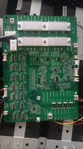
Sounds like you opened it up, are there any identifying marks or labels on the BMS?
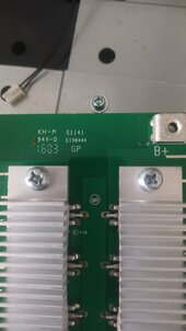
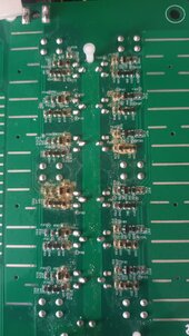
Nothing really. However turning the board upside down it seems to have some corrosion..this is where I wish I had a microscope..
This may explain why there is an issue.

. However im still not 100% sure if its normal behaviour not to have charge at thoese terminal. I guess its not but wanted confirmation from somebody who was familiar wirh these
17208666621667642125868851278930.jpg .
17208666960541853397805839698790.jpg17208667347087286430253826964724.jpg
 
What's the backstory? Was it working previously? Did you just buy it second-hand off eBay or similar. Is it under warrantee?
 
Nothing really. However turning the board upside down it seems to have some corrosion..this is where I wish I had a microscope..
This may explain why there is an issue.

. However im still not 100% sure if its normal behaviour not to have charge at thoese terminal. I guess its not but wanted confirmation from somebody who was familiar wirh these
View attachment 228423 .
View attachment 228424View attachment 228425
Looks to be the flux wasn't cleaned off post construction, order some IPA(isopropyl alcohol) and scrub the board down with hard toothbrush and cross your fingers you don't have to replace
Edit: or warranty it as @SeaGal suggested if you can
 
Looks to be the flux wasn't cleaned off post construction, order some IPA(isopropyl alcohol) and scrub the board down with hard toothbrush and cross your fingers you don't have to replace
Edit: or warranty it as @SeaGal suggested if you can
Yes. It's some sort of film. More like a rubbery varnish. Having ripped off smds before using a hard toothbrush I opted for a sashbrush.

It's knowing if it needs that coms connection for voltage to fo through to chasis connector.
 
Yes. It's some sort of film. More like a rubbery varnish. Having ripped off smds before using a hard toothbrush I opted for a sashbrush.

It's knowing if it needs that coms connection for voltage to fo through to chasis connector.
The rubbery varnish will be conformal coating maybe the BMS has been repaired and wasn't finished properly IE flux not removed and conformal coating wasn't reapplied.
 
I had a board with that rubbery covering, its to protect from moisture but also locks in any residue left after soldering. I had to peel it off but I was only after one resistor. Iso would not affect it so had to resort to thinners, peeled it off after it had softened and then the iso to clean up before soldering. This does not mean you will find the same chemicals work or not work but be prepared to test on a non critical part of the board first.
 
Best way to remove conformal coating is hot air and xylene but I wouldn't recommend them unless your experienced, it's definitely what you would class as a manufacturing default so warranty would be your best bet.
Most Chinese manufactures don't really care aslong as it's obviously their fault if you get in touch ,aybe they will send you a replacement BMS.
 
The history is that it is second hand and in have never had this working. There is no option of waranty especially given its an old battery. Whilst nobody has confirmed, i guess I should expect voltage at thoese terminals when it has been woken up.
 
New BMS would be the quickest option, not that expensive other than the time to sort out the rats nest of existing cables to the cells.
 
New BMS would be the quickest option, not that expensive other than the time to sort out the rats nest of existing cables to the cells.
Any advice. There are 7 packs at 7.4v wirh 3 wires comming from each pack measuring 3.7 or 7.4v. Is this a standard configuration? Which bms would you recommend for an easy swap?
 
What's really bugging me is that exports of bms issues sugest there would be a red light. Mine is green so I hoped it would be simple.
 
Any advice. There are 7 packs at 7.4v wirh 3 wires comming from each pack measuring 3.7 or 7.4v. Is this a standard configuration? Which bms would you recommend for an easy swap?
Only used one BMS, a JK PB BMS but that would be probably overkill. What's odd with your battery is the 14S and the 3.7V so the chemistry is not straight LFP. Your best bet would be a new post asking for recommendations based on the cells, voltage and intended charge and discharge rates. Also what comms you need ie Bluetooth/RS485/Canbus and what balancing capability.

Sparse spec sheet in german


diy solar

diy solar
Back
Top