diy solar

diy solar

30A MPPT DC-DC Charge Controller install

SolarJohngo

New Member
Joined
Dec 14, 2022
Messages
19
Hello,

New to the forum. I'm installing a 30A MPPT DC-DC Renogy Charge Controller. I picked up
a 100W flexible solar panel kit, a 600W inverter, and a Renogy 100aH lithium battery. There is a
negative and postive bus bar with a kill switch for the postive battery.

I need help understanding the mental fog around fuses.

Currently, I have 2 50A ANL fuses.
I am ordering a 15A MC4 inline fuse

My Amazon list has 2 40A circuit breakers bookmarked ( 1 to the Fuse box, and another coming from the solar into the charger)

I'm working with suggestions from Will Prowse's website for the Renogy 400w system, the diagrams on faroutride.com,
and renogy. And from comparing everything, I guessing as to what to do still. So, I'm a bit new to this.

So, for simplicity with out doing too much damage. I think I could run 4 gauge wires for the most part, put 50ANL fuses from Charge Controller
to house battery and another from starter to charge controller. Could I put a 40A circuit breaker from +Bus to fusebox and another coming from
the solar input on the charge controller? What about a breaker going into the alternator positive of the Charge controller (Renogy DCDC30)? Another 40 to 45 seeing
the Vehicle Input Fuse Rating is 45A?


Once this is all connected in my 2012 Tundra, I will upgrade to a second battery and would like to
add another inverter, or single upgraded inverter, to handle heavier loads like an infrared cooktop pulling up to 1200w
on rare ocassions.

As this is being built out I will be adding another Lithium 100aH at the very least after the holidays.
 
There are two calculations you will need to make. What is your 1) max demand for a given period of time and 2) how much energy will you be consuming over a worst case day? I assume 100% off grid? Your on demand needs will point to your inverter output. Then you will factor inputs needed from your PV array and battery bank. Picking up equipment before proper sizing may cause a lot of grief and wasted time. Once you figure out your demands, the system sizing will drive your cable and fuse sizing. You will need a fuse at the PV panel input to the inverter, fuse on positive terminal from batteries to inverter and fuse from inverter output to youf loads panel. Your fuse is rated and sized to protect your wiring, otherwise your wiring becomes the fuse. You may need a battery shunt for safety depending if your battery has self-protection circuitry built in that will kill output if an unbalanced load of short is detected.
 
Makes sense. Thanks for responding.

I think I'll plug in the numbers on the Faroutride calculators after I determine where all the components are going to live in the camper. The calculators automatically determine the proper gauge wire to use. Determining max load shouldn't be too difficult seeing I've used a Inergy kodiak in my previous campers. I can run each item on that and add up the numbers.

I'm not sure what you are saying about a fuse at the PV panel to the inverter. I'll be running a fuse off the positve bus bar to the inverter and an inline fuse from the positive solar 100w to the 30A DC to Dc MPPT charge controller (Renogy). I believe the shunt is not required with the Renogy controller. The controller has multiple protection functions. I will check out and reread the manual. I just received the controller today.

Let me take the time this evening to enter in the wire lengths. I'll take a screenshot and write notes in Photoshop to clarify things.
You have it right. Check the inverter spec for PV V+A protection. Mine wants 600V+30A. Make sure all your wire is pure copper and not CCA. I used TEMCO brand on Amazon for battery and PV wiring and highly recommend. Best -Jay
 
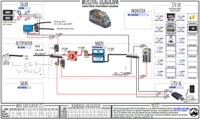
Uploaded the far out ride diagram. I entered in the info and it calculates sizes and fuses.

I went outside in the misty rain to measure a few things and make quick guesses as to where to postion everything. Because there is a diesel heater being installed in the truck bed of the Tundra GFC camper, I'm putting the electrical on a board where the rear seats were located in the double cab. lessens the instance of a flammable disaster occurring.

After the fuse box, I can run marine grade wires out and thru a grommet hole in the front of the bed channeling a wire loom underneath the cab.

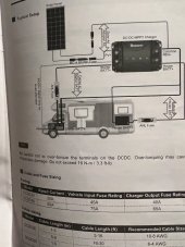
I already have 20ft 6AWG with lugs. I figure that can be accurately measured from the starter battery to the charge controller in the double cab without connecting anything. If someone chimes in and thinks that would be sufficient. Farout Ride's calcutator suggests 4AWG but the Renogy manual for the Controller says 10-8AWG for anything under 16ft -3ft. 16 to 30 ft would be 6AWG -4. Seeing I already have 6AWG, why not use it there?

Also note the inverter says 1000W. I picked up a 600W on Amazon and may look into installing a much bigger inverter if I discover I like the infrared cooktop which can use 1200 to 1800W.
 
Ideally, there will be 300 watt if you include the already installed 100w inergy panel however that is occasionally connected to the Inergy Kodiak which I use to power the marine fridge, lights coffee grinder etc. I can always use that as back and or have the new system charge the Inergy unit
at night if the temperatures in the tent/cab are above freezing.
 
You can not run panels in series into that controller if you decide to add more panels.
 
Thanks good observation. The Renogy manual is very vague about it. I believe it was mentioned in a you tube video but I haven't
ironed it out yet. Initial setup is only one flexable 100W for I don't believe I need an inline fuse legally seeing the panel or even panels
aren't exceeding t 15A. I just watched

How to Fuse a Solar Panel Array for a DIY Camper Electrical System​

by explorist life and that seems to be the standard. I dunno. I'll drink lots of coffee when installing and hope for the best.

After everything is installed I want to make an appointment at my local RV service center to have an electrician look over my
system. So, far I'm seeing baby step improvements in the planning with more roadblocks to come.
 
Uploaded the far out ride diagram. I entered in the info and it calculates sizes and fuses.

I went outside in the misty rain to measure a few things and make quick guesses as to where to postion everything. Because there is a diesel heater being installed in the truck bed of the Tundra GFC camper, I'm putting the electrical on a board where the rear seats were located in the double cab. lessens the instance of a flammable disaster occurring.

After the fuse box, I can run marine grade wires out and thru a grommet hole in the front of the bed channeling a wire loom underneath the cab.

I already have 20ft 6AWG with lugs. I figure that can be accurately measured from the starter battery to the charge controller in the double cab without connecting anything. If someone chimes in and thinks that would be sufficient. Farout Ride's calcutator suggests 4AWG but the Renogy manual for the Controller says 10-8AWG for anything under 16ft -3ft. 16 to 30 ft would be 6AWG -4. Seeing I already have 6AWG, why not use it there?

Also note the inverter says 1000W. I picked up a 600W on Amazon and may look into installing a much bigger inverter if I discover I like the infrared cooktop which can use 1200 to 1800W.
Go big, or go home is what I say. Plan for worst case, much easier to do now than have to upgrade later
 
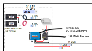
There's a lot in this thread and diagram but I'd like to focus on this one part:

1671129214486.png

The current coming out of a charge controller is higher than the current that goes into a charge controller, that's their whole thing. Big voltage small current becomes small voltage and bigger current.

So I am puzzled why you [they] have chosen your low amperage side to have such heavier wiring than your high(er) amperage side?
You should have about 16 amps on the downstream side and you've got 12AWG spec'd and a breaker for 25 amps. That's all good, the charge controller won't slug out a full 30 amps with this PV setup anyway.

It's the solar panel side that seems off. 8 AWG is significantly larger than the 12 AWG on the other side and it'll be carrying significantly less current.

Edit- I didn't fully appreciate that this was some third party app screenshot that was helping you, not your own personal design. That said, I still don't think what is on the screen is an appropriate or efficient design. I'm not sure I'd trust that website.
 
Last edited:
The solar is confusedly vague. another 100w flexible panel is a January upgrade. I'm getting that Explorist life is suggesting from his You tube
is to not fuse or circuit break a system this small and to add a solar disconnect instead .

https://www.explorist.life/how-to-wire-a-solar-disconnect-for-a-diy-camper-electrical-system/

This is more likely the final senario.

This is a screen shot of the wiring diagram that I downloaded and is interactive with Adobe Arcrobat. The fault is mine for not being clear.
I have not test run the cables to get accurate measurements. Included with the solar panel is 20ft of cable already.
Go big, or go home is what I say. Plan for worst case, much easier to do now than have to upgrade later
So, I should add a 2000w inverter for future potential infrared cooking and perhaps 3 batteries? I'm still not finalized the maximum load. I think a 600w for most uses and turning on a 2000w for heavy uses would make sense but may be too confusing for my noobish abillites with 2 inverters ( or I could sell the 600W).

With the solar generator alone, I've had to check into a state park campground after several days of rain and splurged for shore power. The car charger for the Inergy Kodiak isn't recommended to use because its known for damaging the battery so I don't use it. I think with the solar generator and a moderately sized solar + DCDC charger I can charge the Kodiak, Starter battery and house batteries thus extending the length of staying out and about.
 
Last edited:
I'm still not pulling the trigger on cabling or fuses until places for all the 12V loads are figured out
and the total max load.

A Halcory diesel heater arrived today. I wired it to a cigarette adapter plug for testing on the Kodiak.
 
I'm still not pulling the trigger on cabling or fuses until places for all the 12V loads are figured out
and the total max load.

A Halcory diesel heater arrived today. I wired it to a cigarette adapter plug for testing on the Kodiak.
Making progress!
 
A number of items have arrived this week. I'm beginning my time off so I can devote more time to it. I printed out several bare bones wiring diagrams so I can scribble notes. First and foremost, I wired the diesel heater to a cigarette plug adapter and will put exhaust wrap around the
exhaust. Once I get an accurate power draw I will write down the info from the inergy kodiak screen and instruction specifications. I picked up marine grade 14 and 16 gauge to wire LEDs, interior lights, the fridge, diesel heater etc.

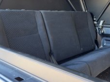
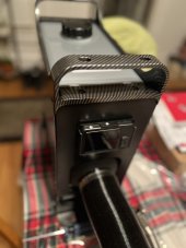
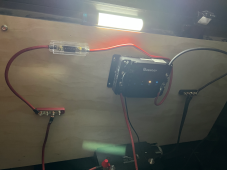
I removed the back seat in the Tundra double cab and I will put up an electriclal fuse panel board in its place . The seat is pictured
now as a jump seat for couch style dinning and lounging. I will secure it down shortly with L-track once the bolts arrive.
seats.jpg
 
I'd like to set up this simple system with the 20ft of 6 gauge I have cut to length from the starter battery to the double cab
fuse panel location tomorrow without any solar. That way I will test the charger and Lithium battery looking for issues and/or
errors.
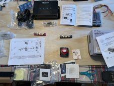
Renogy_manual.JPG
 
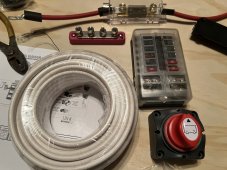
The most complex I will get tomorrow is to add a kill switch and mount the 12V fuse box without connecting it to anything. Simply
to begin building out the marine grade wiring, adding fuses once the load is determined, and place 12V loads inside the camper in
their corresponding permanent locations. There is a lot of testing that can be done with this initial setup confirming if the controller
is working as well as the Bluetooth app connection. The order list this week will include a 250A fuse, a 40A circuit breaker to the fuse
panel and other gauge wire (2/0 AWG) especially.
ren_pos.JPGmarine_grade.JPG
 
There's a lot in this thread and diagram but I'd like to focus on this one part:

View attachment 124824

The current coming out of a charge controller is higher than the current that goes into a charge controller, that's their whole thing. Big voltage small current becomes small voltage and bigger current.

So I am puzzled why you [they] have chosen your low amperage side to have such heavier wiring than your high(er) amperage side?
You should have about 16 amps on the downstream side and you've got 12AWG spec'd and a breaker for 25 amps. That's all good, the charge controller won't slug out a full 30 amps with this PV setup anyway.

It's the solar panel side that seems off. 8 AWG is significantly larger than the 12 AWG on the other side and it'll be carrying significantly less current.

Edit- I didn't fully appreciate that this was some third party app screenshot that was helping you, not your own personal design. That said, I still don't think what is on the screen is an appropriate or efficient design. I'm not sure I'd trust that website.

Voltage drop (=wire AWG) is determined by current AND wire length. In the screenshot, you can see that the wires going from the panels to the solar controller are 10FT each (20FT return), and the wires going from the solar controller to the battery bank are only 1FT each (2FT return). Hence the smaller gauge on the higher amperage side :)
Most diagrams online don't take the length into account, because it's quite complicated to implement. This one does :)
 
Last edited:
Voltage drop (=wire AWG) is determined by current AND wire length. In the screenshot, you can see that the wires going from the panels to the solar controller are 10FT each (20FT return), and the wires going from the solar controller to the battery bank are only 1FT each (2FT return). Hence the smaller gauge on the higher amperage side :)
Most diagrams online don't take the length into account, because it's quite complicated to implement. This one does :)
It's specifying 8 AWG for roughly 8 amps running 10 feet. That's an oversized miscalculation. How can someone trust a widget that is so expensively mal-designed?
 
Voltage drop (=wire AWG) is determined by current AND wire length. In the screenshot, you can see that the wires going from the panels to the solar controller are 10FT each (20FT return), and the wires going from the solar controller to the battery bank are only 1FT each (2FT return). Hence the smaller gauge on the higher amperage side :)
Most diagrams online don't take the length into account, because it's quite complicated to implement. This one does :)
That's cool if you want to focus on that. However, I'm not connecting the solar for a while. I may have not been clear about that. I'm still at the testing phase and the most accurate diagram I'm using at the moment is the Renogy manual without any solar. I simply want to know if the charge controller is working and the battery can take a charge and be maintained. I can setup a simple DC to DC charger system with a shutoff for cold temps before I return to work after the holiday vacation. That way I can test the battery and might return it if I determine the more expensive self heating battery is necessary. For now a bluetooth temp monitor will be in the cab and I will shutoff if it goes below freezing.

The offline PDF file by Far-out ride is what I'll be using once I get accurate data from my 12V loads. So, I'm installing the loads and testing each with an Inergy Kodiak and then make final decisions about wire gauge. If you noticed the printed out diagram from FarOutRide is on the plywood picture and that has no solar in the schematic it also lists 3 batteries and I only have 1 at the moment. So, don't rely on the first part of the post. I should delete, edit or repost a more current setup. That will probably happen in the new year.

Anyhoo thanks for the input.
 
Last edited:
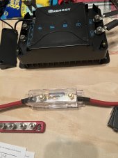
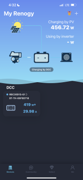
I've had very little time to dedicate to my electrical build so in order to see if the Renogy 30A DC to DC charger works and the Lithium battery is good. I decided to do a simple setup. And the verdict is the system is working.

I used mostly 6 AWG wire which the manual recommend 8 for the distance covered. Another truck camper you tuber has an identical setup and Renogy told him to use a 50A fuse seeing 45A are hard to come by. So, I have 2 50 A. I'll attach the connection to the battery. Running cable thru the firewall was the most sketchy part.

I'll post the Renogy DC home app first run which probably not accurate but confirms its working.

I activated the lithium battery from shelf mode after all the connections were made. Then selected the lithium profile which is a blue LED indicator.

All is operational.

The noticeable difference is I no longer have dimming of my headlights and all the electrical is much more responsive. I hope I'm not going to fry or damage anything.
 
Last edited:

diy solar

diy solar
Back
Top