justinm001
Solar Addict
- Joined
- Dec 18, 2022
- Messages
- 1,572
I'm about to start my 48V addition and need some double checking and ideas. Currently I have all Victron: CerboGX with 50touch, 150/100 MPPT, Lynx, power in, 2x Lynx Distribution, Lynx shunt all 1000a. Smartshunt 500a, 12V Quattro 5000w 120V inverter, 48V Quattro 5000w 120V inverter. 2xEG4-LL 12V 400AH batteries and 2xSOK 48V 100AH batteries (on order). 18 Renogy 100w panels (6x3 setup) installed and another 12 panels waiting to be installed will order 6 more so 3600w total on roof, have 2x320w panels extra maybe for trailer roof? Both inverters are rated for 100a on each of the 2 inputs and outputs. I have a 20k 240v genny and normal 50amp 240v shore connection. 12V 300a dedicated 50DN alternator with WS500 setup for lithium profile No 240V devices on coach and have 12V lighting.
I use this coach mainly for day or weekend trips and plan on using its solar/batteries almost exclusively. Have about 150w constant drain from various devices when not in use and about 15kWh per day when in use. Have 20kW total battery power and make about 10kW per day in solar. Sunny days mean more solar but more AC so more usage. Depending on where we camp we might have free shore power. We also get freeish alternator power while driving. I use it at least once a week.
Plan is to run shore and genny to both inputs of the 48V inverter then run from Out1 of 48V to input1 of 12V inverter and use powerassist to be able to get 10kw inverter power as needed to both outputs of the 48V inverter which feed into each leg on the breaker boxes. I'll have a black to out1, red to out2, white to neutral, and bare to ground going from inverter to breaker panel 1 then from panel 1 to panel 2. Im unsure of the gauge wires to the panel or between the panels.
With this setup it seems I'm limited to the output neutral wire gauge as if I have 6/3 wire i'll be limited to a 55/60 amp max and if 4/3 i'll be at 100amp max. If I want to be able to safely pump out 100amps on each side or max my genny 20k output limit what is the best option? Or am I incorrect and neutral amperage not as important?
Also with this setup I'll have 50amps coming from shore to in1 on 48V, could I also have 50amps coming from shore to in2 on the 12V with both grounds and commons shared? Or would I need to set the limit to 25 amps for each?
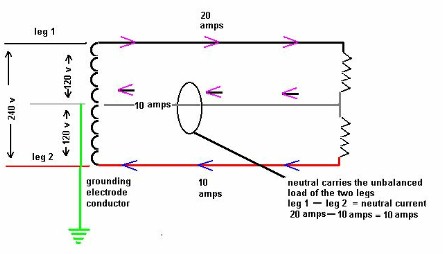
I'm a bit confused at the setup as I have 6 AC units running 15amps with a LRA of 50amps and the coach was setup to run a lot of equipment all over the genny and all 120V. The load was evenly distributed over both legs but still share the common which are all the same gauge.
As far as the configuration, i'm thinking I'll need to get a 2nd Cerbo, setup the solar on 48V and keep both systems separate. The idea is I want it to drain the 48V power first then use the 12V power since it shares lighting.
How low should I allow the SoC get on the 48V before I disable its outputs?
How should I best program the 12V system so it'll use the 48V inverter power first but not use?
If I have it set to keep the 12V at 100% then I lose freeish alternator charge when I'm driving. Any tips on programming to get it to use this power too? Like if 48V batteries are under 75% SoC and alternator is on then use 12V power as long as its 90%+
I use this coach mainly for day or weekend trips and plan on using its solar/batteries almost exclusively. Have about 150w constant drain from various devices when not in use and about 15kWh per day when in use. Have 20kW total battery power and make about 10kW per day in solar. Sunny days mean more solar but more AC so more usage. Depending on where we camp we might have free shore power. We also get freeish alternator power while driving. I use it at least once a week.
Plan is to run shore and genny to both inputs of the 48V inverter then run from Out1 of 48V to input1 of 12V inverter and use powerassist to be able to get 10kw inverter power as needed to both outputs of the 48V inverter which feed into each leg on the breaker boxes. I'll have a black to out1, red to out2, white to neutral, and bare to ground going from inverter to breaker panel 1 then from panel 1 to panel 2. Im unsure of the gauge wires to the panel or between the panels.
With this setup it seems I'm limited to the output neutral wire gauge as if I have 6/3 wire i'll be limited to a 55/60 amp max and if 4/3 i'll be at 100amp max. If I want to be able to safely pump out 100amps on each side or max my genny 20k output limit what is the best option? Or am I incorrect and neutral amperage not as important?
Also with this setup I'll have 50amps coming from shore to in1 on 48V, could I also have 50amps coming from shore to in2 on the 12V with both grounds and commons shared? Or would I need to set the limit to 25 amps for each?
I'm a bit confused at the setup as I have 6 AC units running 15amps with a LRA of 50amps and the coach was setup to run a lot of equipment all over the genny and all 120V. The load was evenly distributed over both legs but still share the common which are all the same gauge.
As far as the configuration, i'm thinking I'll need to get a 2nd Cerbo, setup the solar on 48V and keep both systems separate. The idea is I want it to drain the 48V power first then use the 12V power since it shares lighting.
How low should I allow the SoC get on the 48V before I disable its outputs?
How should I best program the 12V system so it'll use the 48V inverter power first but not use?
If I have it set to keep the 12V at 100% then I lose freeish alternator charge when I'm driving. Any tips on programming to get it to use this power too? Like if 48V batteries are under 75% SoC and alternator is on then use 12V power as long as its 90%+